
Dealing with electrical issues in modern vehicles can be a daunting task, especially when it involves the Engine Control Unit (ECU). Short circuits are a common culprit behind many electrical malfunctions, and understanding how to diagnose them in circuits connected to your car’s ECU is crucial for effective auto repair. As an automotive repair specialist at cardiagnostictool.store, I’ve seen firsthand how frustrating these problems can be. This guide will walk you through the process of identifying short circuits in your Circuit Ecu Car, providing you with the knowledge to tackle these issues systematically.
Modern vehicles rely heavily on complex electrical systems managed by the ECU. This sophisticated computer controls various engine and vehicle functions, and its circuits are intricate and sensitive. When a short circuit occurs within an ECU-connected circuit, it can lead to a range of problems, from blown fuses to malfunctioning components and even potential damage to the ECU itself. Therefore, accurate diagnosis is the first step towards effective repair.
When it comes to identifying short circuits, manufacturers typically provide structured methods. These methods often differentiate between circuits that are connected to a control unit (like the ECU) and those that are not. Let’s explore these approaches to help you pinpoint the source of the problem in your circuit ecu car.
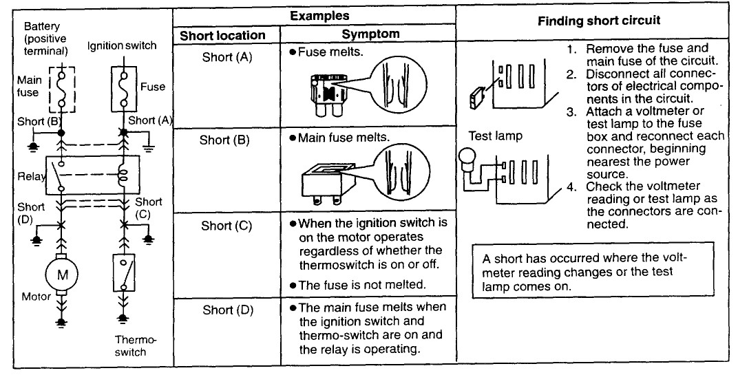
For circuits not directly connected to a control unit, a common diagnostic method involves isolating the circuit and using a voltmeter to track down the short. The process generally looks like this:
- Fuse Removal: Begin by removing the fuse associated with the circuit in question, as well as the main fuse for that system.
- Component Disconnection: Disconnect all electrical connectors of components within the affected circuit. This step is crucial to isolate different sections of the circuit.
- Voltmeter Connection and Reconnection: Attach a voltmeter to the fuse box terminals for the circuit you are testing. Then, systematically reconnect each connector, starting from the component closest to the power source.
- Reading Changes Indicate Short: Observe the voltmeter reading as you reconnect each component. A change in the voltmeter reading during reconnection pinpoints the area where the short circuit is located. This change indicates that you have just reconnected the section of the circuit containing the short to the power source.
This method is effective for simpler circuits. However, when dealing with circuits connected to the ECU, the diagnostic approach needs to consider the control unit’s influence. Here’s a manufacturer-recommended method for these more complex scenarios:
- Voltmeter to CPU Connector: Attach your voltmeter to the connector of the CPU (ECU) that is relevant to the circuit you are testing.
- Connect to Switch/Sensor Connector: Connect the other voltmeter lead to the connector of a switch or sensor within the same circuit.
- Zero Volt Reading Indicates Short: A voltmeter reading of 0V in this setup suggests a short circuit. This is because a short to ground would create a path of least resistance, resulting in minimal voltage difference between the ECU connector and the switch/sensor connector.
Understanding wiring diagrams is paramount when troubleshooting circuit ecu car issues. These diagrams are your roadmap to the vehicle’s electrical system. They detail how different components are connected, including fuses, relays, sensors, actuators, and the ECU itself. Fuses are critical safety devices in any circuit ecu car. In the example from the original post, multiple fuses are mentioned, including engine fuses and meter fuses. When diagnosing, it’s essential to identify all fuses related to the circuit in question by consulting the wiring diagram. The voltmeter readings should ideally be taken at the fuse connector that is directly in line with the section of the circuit you are currently testing, as indicated by the wiring diagram.
Let’s consider the example of the Intake Manifold Runner Control (IMRC) circuit discussed in the original post. The provided schematics are invaluable for understanding this specific circuit ecu car configuration.
Voltage drop readings are another important aspect of diagnosing circuit ecu car issues. Manufacturers often provide specified voltage drop values for different points in a circuit under various operating conditions. Comparing your measured readings against these specifications can help pinpoint abnormalities. For instance, the original post provides voltage drop specifications for the IMRC terminals at idle and at 3300 RPM. Deviations from these values can indicate problems within the circuit, potentially including short circuits or component failures.
In the postscript of the original article, the author discovered persistent short circuits related to the oxygen sensors, which were ultimately traced back to a faulty ECU. This highlights a critical point: sometimes, short circuits can damage the ECU, or what appears to be a short circuit might actually be an internal ECU malfunction. The final diagram in the original post illustrates a potential fault within the ECU itself, between IMRC Terminal 1 and PCM Pin 42.
In conclusion, troubleshooting short circuits in a circuit ecu car requires a systematic approach, a good understanding of wiring diagrams, and careful use of diagnostic tools like voltmeters. By following manufacturer-recommended procedures and paying close attention to voltage readings, you can effectively diagnose and address these challenging electrical problems. Remember to always consult your vehicle’s specific service manual for accurate wiring diagrams and diagnostic procedures relevant to your particular make and model. For advanced diagnostics and ECU related issues, professional tools from cardiagnostictool.store can provide invaluable support in ensuring accurate and efficient repairs.