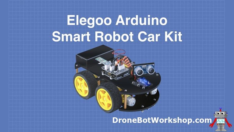
Embarking on the journey of Arduino and robotics often leads enthusiasts to an exciting milestone: building their own robot car. It’s a project that not only imparts invaluable skills in electronics and mechanics but also offers a tangible and impressive result. For those venturing into this realm, the Elegoo Smart Robot Car emerges as an exceptional platform. This kit simplifies the complexities often associated with robot car projects, providing a user-friendly experience without compromising on functionality or learning opportunities.
While constructing a robot car from scratch can present hurdles, particularly for beginners – from sourcing components and drilling for mounting to intricate wiring and soldering – kits like the Elegoo Smart Robot Car offer an elegant solution. These kits consolidate all necessary parts, ensuring compatibility and streamlining the building process. The Elegoo kit stands out with its comprehensive nature and high-quality components, promising a rewarding experience in building a functional robot car.
This article will guide you through the assembly and, more importantly, the programming aspects of the Elegoo Smart Robot Car Version 3.0. We’ll delve into how to bring this smart vehicle to life not just mechanically, but intellectually, by exploring the fundamentals of Elegoo Robot Car Programming. This kit isn’t just about putting parts together; it’s about learning to control and command your creation through code.
Alt text: Assembled Elegoo Smart Robot Car, showcasing its compact design and electronic components, ready for Arduino programming.
Discovering the Elegoo Smart Robot Car Kit
The Elegoo Smart Robot Car isn’t just another robot kit; it’s a feature-rich platform designed to introduce you to the fascinating world of robotics and programming. It boasts an impressive array of functionalities right out of the box:
- Agile 4-Wheel Drive: Provides robust and versatile movement.
- Infrared (IR) Remote Control: For immediate, direct control.
- Bluetooth Connectivity: Enables wireless control via smartphones or other Bluetooth devices.
- Intelligent Ultrasonic Collision Avoidance: Allows the robot to navigate its environment autonomously.
- Line Following Capability: For programmed path navigation.
- Rechargeable LiPo Batteries: Ensures extended operation and includes a dedicated charger.
- Solder-Free Assembly: No soldering or specialized tools are required, making it accessible for beginners.
Coupled with clear, step-by-step instructions and readily available Arduino code examples, the Elegoo Smart Robot Car kit is perfectly tailored for Arduino enthusiasts across all skill levels, especially those keen on diving into Elegoo robot car programming.
Unboxing the Elegoo Smart Robot Car
The Elegoo Smart Robot Car kit arrives in a durable and reusable orange case, thoughtfully organized to keep all components secure and accessible. Inside, you’ll find a neatly compartmentalized layout, with a component diagram conveniently placed on the inner lid for easy inventory.
Alt text: Unboxed Elegoo Smart Robot Car kit displaying organized components including Arduino Uno, motors, sensors, and electronic modules, ready for assembly.
The kit includes:
- Elegoo Arduino Uno R3 – The brain of your robot, programmable and versatile.
- Top and Bottom Acrylic Chassis Plates – Forming the structure of the robot car.
- Four DC Motors & Four Tires – For movement and locomotion.
- Custom Arduino Shield – Integrating essential functionalities and simplifying connections.
- L298N Motor Controller – Managing motor speed and direction for precise movement.
- 3-Channel Line Sensor Module – Enabling line following capabilities.
- SG90 Servo Motor – For mounting and controlling the ultrasonic sensor’s direction.
- HC-SR04 Ultrasonic Distance Sensor – Providing obstacle detection for autonomous navigation.
- Bluetooth Module – Facilitating wireless control and communication.
- Two 18650 LiPo Batteries & Battery Holder – Powering the robot car.
- Battery Charger – For recharging the LiPo batteries.
- Connection Cables – Ensuring easy and reliable connections between modules.
- USB Cable for Arduino – For programming and communication with the Arduino Uno.
- IR Remote Control – For immediate, infrared-based control.
- Servo & Ultrasonic Sensor Mounting Brackets – For secure sensor attachment.
- Assembly Hardware – Including screws, nuts, and standoffs, categorized for each assembly step.
- Three Screwdrivers & Vinyl Electrical Tape – Providing necessary tools for assembly.
- CD ROM – Containing code examples, detailed manuals, and resources to get you started with Elegoo robot car programming.
A standout feature is the organized packaging of hardware, separated into labeled bags for each assembly stage. This thoughtful detail greatly simplifies the construction process, making it less intimidating, especially for beginners eager to start Elegoo robot car programming.
Now that we’ve inventoried the kit’s contents, let’s move on to assembling the Smart Robot Car, preparing it for the exciting phase of programming.
Assembling Your Smart Robot Car: A Step-by-Step Guide
Assembling the Elegoo Smart Robot Car is a straightforward process, largely thanks to the comprehensive and well-illustrated PDF manuals included. These resources, along with sample code, are conveniently provided on the included CD-ROM and are also available for download from the Elegoo website, ensuring you have access to the latest versions.
For this guide, we recommend downloading the manuals and code to ensure you’re working with the most up-to-date instructions and software for your Elegoo robot car programming journey.
The kit thoughtfully includes the essential tools for assembly: two small Phillips screwdrivers and a 2.5mm hex key. While these are sufficient, you might find a pair of pliers helpful for certain steps, though they are not strictly necessary.
Elegoo has streamlined the assembly by pre-packaging the hardware into clearly labeled bags for each assembly section. This thoughtful organization significantly simplifies the process.
Mounting Motors and Motor Mounts to the Chassis
The initial step involves attaching the aluminum mounting blocks to each of the four DC motors. Use the longer screws to secure these blocks, ensuring they are placed on the side of the motor where the connection cables protrude. The blocks are symmetrical, so orientation isn’t critical, as the mounting holes for chassis attachment are on both sides.
Once the mounting blocks are on, you can fix the motors to the bottom base plate. Remember to peel off the protective film from both sides of the base plate. Identify the side marked “A”—this is the top side.
Alt text: Close-up of DC motors with aluminum mounting blocks being attached to the acrylic chassis base plate, first step in Elegoo robot car assembly.
Attach the motors to the base plate using the mounted blocks. Insert screws through the base plate into the threaded holes of the aluminum blocks and tighten them. Ensure the motors are aligned with the base plate’s edge before final tightening. Keep the base plate accessible as it will be used in the next stage.
L298N Motor Controller Board Installation
The L298N module, a crucial component for Elegoo robot car programming, acts as an H-Bridge driver, enabling control of the DC motors. The version included in this kit is customized with dual connectors for each motor output, accommodating the parallel wiring of motors on each side of the robot car. It also features connectors for necessary power and data cables.
Position the L298N board with its heatsink facing the rear of the chassis.
Mount the board onto the bottom base plate using four M3x14 screws and small spacers. Thread the screws through the L298N mounting holes, then add the spacers, and finally insert them through the base plate holes. Secure everything with four M3 nuts.
Alt text: L298N motor driver board mounted on the robot car chassis and connected to DC motors, essential for motor control in Elegoo robot car programming.
After securing the L298N, connect the four motors to their corresponding connectors. These connectors are designed to prevent incorrect insertion, simplifying the wiring process.
Mounting the Line Follow Sensor
Next, we’ll install the line follow sensor array on the bottom base plate. This sensor is vital for enabling line following behavior in your Elegoo robot car programming projects. It mounts underneath the chassis using four threaded spacers, four M3x7 screws, and four M3 nuts.
Alt text: Line follow sensor array being installed underneath the robot car chassis, enabling line tracking functionality for programmed navigation.
Ensure the line follow sensor array is oriented so that the sensitivity adjustment potentiometer faces the front of the robot car. This placement positions the sensor’s connector near the chassis’s large hole, which is designed for cable routing.
Attaching the Arduino to Top Chassis and Shield
Now, switch to the top chassis plate. Like the bottom plate, it comes with a protective layer that needs to be removed.
Crucially, note the label on the protective covering indicating the upward-facing side. Correct orientation is vital for the top plate; otherwise, you’ll need to disassemble and restart, which is best avoided!
Alt text: Arduino Uno microcontroller board mounted on the top chassis of the Elegoo robot car, serving as the programmable brain for the robot.
The first component to mount on the top chassis is the Arduino Uno. Use three M3x14 screws and three spacers, as one of the Arduino’s mounting holes is not used. Secure the screws with three M3 nuts.
Alt text: Custom Arduino shield being mounted on top of the Arduino Uno, expanding functionalities and simplifying connections for Elegoo robot car programming.
After mounting the Arduino Uno, install the custom interface shield. Align the shield’s pins carefully with the Arduino’s headers before pressing it into place.
Alt text: Arduino shield fully mounted on the Arduino Uno, providing integrated motor control, sensor interfaces, and power distribution for the Elegoo robot car project.
Installing the Battery Compartment
The battery compartment is the next component to add to your Smart Robot Car. Use four M3x10 screws to mount the holder. These screws have Phillips heads, so use the appropriate screwdriver from the kit.
Remove the top of the battery compartment to access the screw holes. It’s also necessary to have it open for battery installation later!
Alt text: Battery compartment being installed on the top chassis of the Elegoo robot car, designed to securely hold and power the robot with LiPo batteries.
Align the holder flush with the top plate edges, then insert and secure the screws with four M3 nuts.
Once mounted, install the two 18650 LiPo batteries, ensuring correct polarity as indicated inside the battery compartment. While they are pre-charged, you might want to fully charge them using the provided charger before extensive use. Close the battery compartment cover once the batteries are in place.
Finally, connect the battery holder to the power connector on the shield. Ensure the power switch is in the “off” position before connecting to avoid accidental power-up.
Servo Motor Installation
The servo motor, essential for directing the ultrasonic sensor, is next. Mount it onto a separate small plate included with the ultrasonic sensor holder. Attach the servo to this plate using two small M2x10 screws and M2 nuts, inserting the screws from the plate’s underside. Refer to the manual for correct servo orientation.
After securing the servo to its plate, mount this assembly to the top chassis plate using three M3x10 screws and M3 nuts.
Alt text: SG90 servo motor mounted on its bracket on the Elegoo robot car chassis, used for directional control of the ultrasonic sensor.
After positioning the servo, route its cable through the designated hole in the top plate and connect it to the shield connector. Ensure correct orientation, aligning the servo’s brown ground wire with the shield’s ground pin, as indicated on the shield.
Ultrasonic Sensor Mounting
The ultrasonic sensor, crucial for obstacle avoidance in Elegoo robot car programming, is mounted next. Attach it to its mounting bracket using four tiny M1.6×8 screws. These require the smallest Phillips head screwdriver from the kit.
Once the ultrasonic sensor is on its bracket, attach the assembly to the servo motor shaft. Align the sensor to face forward, ensuring it meshes with the servo shaft gear. Precise alignment might require slight adjustment to ensure proper gear engagement.
Alt text: HC-SR04 ultrasonic sensor mounted on the servo motor, enabling distance sensing for obstacle avoidance in Elegoo robot car programming.
Connect the provided 4-conductor cable to the sensor and then to the shield. This is the only 4-conductor cable in the kit, making it easily identifiable, and like other cables, it’s keyed for correct orientation.
The small screw for securing the bracket to the servo shaft is included with the SG90 servo package, along with extra servo horns and screws not needed for this kit – keep these for future projects.
Cable Management and Wiring
Your robot car is now visibly taking shape! It’s time for wiring and cable management, crucial for both functionality and aesthetics.
Before connecting the components, install the six copper spacers that will join the bottom and top plates. Mount these onto the bottom plate using six M3x10 screws. The top plate will be attached to these spacers later.
The cables in the kit are uniquely designed to prevent misconnections. However, the manual’s illustrations are a helpful guide if you’re unsure.
Start with the Line Follower sensor. Connect one end of its cable to the sensor board and route it through the hole in the base plate. Leave the other end disconnected for now.
Next, address the L298N motor driver, which requires a power and an interface cable. Identify these unique cables and connect them to the L298N, leaving the other ends free for now.
Alt text: Top and bottom chassis plates being joined together with cables routed through, preparing for final connections in the Elegoo robot car assembly.
Route all the cables you’ve connected from the base plate components up through the hole in the top base.
Now, use the six remaining M3x10 screws to fasten the top plate to the copper spacers, effectively joining the two chassis plates.
Finally, connect all the loose cable ends to their respective, clearly labeled connectors on the shield.
Bluetooth Module Installation
Installing the Bluetooth module is remarkably simple. It features a connector that directly mates with a socket on the shield. Just plug it in, and it’s securely connected!
A crucial point to remember for Elegoo robot car programming: the Bluetooth module must be removed when programming the Arduino. It shares the serial data line with the Arduino USB connector, and leaving it connected will cause conflicts during programming.
Tire Installation
The final step in assembling your Elegoo Smart Robot Car is attaching the tires to the motor shafts. The shafts are keyed to match the mounting holes in the tires, ensuring a secure fit.
Press each tire firmly onto a motor shaft, then secure it using a long M2x25 screw. These screws are Phillips head, so use the correct screwdriver from the kit.
Alt text: Fully assembled Elegoo Smart Robot Car, showcasing all components in place and ready for operation and Elegoo robot car programming.
Your robot car is now fully assembled and ready to transition from mechanics to the exciting world of Elegoo robot car programming!
Basic Testing and First Steps in Elegoo Robot Car Programming
With the Elegoo Smart Robot Car assembled, it’s time to ensure everything is functioning correctly. For this initial test, we’ll focus on basic movement. In subsequent sections, we’ll explore more advanced features like Bluetooth control, IR remote operation, line following, and collision avoidance, all driven by Elegoo robot car programming.
Elegoo provides sample code on the included CD-ROM and on their website. Lesson one, “make the car go,” is an excellent starting point. This lesson includes several code examples:
- forward_back.ino: Demonstrates forward and backward motion.
- left_wheel_rotation.ino: Controls the left wheels independently.
- right_wheel_rotation.ino: Controls the right wheels independently.
- speed_control.ino: Illustrates speed variation and stopping.
- AUTO_GO.ino: Executes a sequence of movements in all directions.
These examples are designed to introduce you to controlling the L298N motor controller, a fundamental aspect of Elegoo robot car programming. If you’re unfamiliar with the L298N H-Bridge motor controller, resources are available online to help you understand its operation.
We’ll examine the AUTO_GO.ino sketch to test our Elegoo Smart Robot Car. Before uploading any code, remember to disconnect the Bluetooth module to avoid programming conflicts.
AUTO_GO.ino Code Breakdown:
//www.elegoo.com
// The direction of the car's movement
// ENA ENB IN1 IN2 IN3 IN4 Description
// HIGH HIGH HIGH LOW LOW HIGH Car is runing forward
// HIGH HIGH LOW HIGH HIGH LOW Car is runing back
// HIGH HIGH LOW HIGH LOW HIGH Car is turning left
// HIGH HIGH HIGH LOW HIGH LOW Car is turning right
// HIGH HIGH LOW LOW LOW LOW Car is stoped
// HIGH HIGH HIGH HIGH HIGH HIGH Car is stoped
// LOW LOW N/A N/A N/A N/A Car is stoped

//define L298n module IO Pin
#define ENA 5
#define ENB 6
#define IN1 7
#define IN2 8
#define IN3 9
#define IN4 11

void forward(){
  digitalWrite(ENA,HIGH);//enable L298n A channel
  digitalWrite(ENB,HIGH);//enable L298n B channel
  digitalWrite(IN1,HIGH);//set IN1 hight level
  digitalWrite(IN2,LOW);  //set IN2 low level
  digitalWrite(IN3,LOW);  //set IN3 low level
  digitalWrite(IN4,HIGH);//set IN4 hight level
  Serial.println("Forward");//send message to serial monitor
}

void back(){
  digitalWrite(ENA,HIGH);
  digitalWrite(ENB,HIGH);
  digitalWrite(IN1,LOW);
  digitalWrite(IN2,HIGH);
  digitalWrite(IN3,HIGH);
  digitalWrite(IN4,LOW);
  Serial.println("Back");
}

void left(){
  digitalWrite(ENA,HIGH);
  digitalWrite(ENB,HIGH);
  digitalWrite(IN1,LOW);
  digitalWrite(IN2,HIGH);
  digitalWrite(IN3,LOW);
  digitalWrite(IN4,HIGH);
  Serial.println("Left");
}

void right(){
  digitalWrite(ENA,HIGH);
  digitalWrite(ENB,HIGH);
  digitalWrite(IN1,HIGH);
  digitalWrite(IN2,LOW);
  digitalWrite(IN3,HIGH);
  digitalWrite(IN4,LOW);
  Serial.println("Right");
}

//before execute loop() function,
//setup() function will execute first and only execute once
void setup(){
  Serial.begin(9600);//open serial and set the baudrate
  pinMode(IN1,OUTPUT);//before useing io pin, pin mode must be set first
  pinMode(IN2,OUTPUT);
  pinMode(IN3,OUTPUT);
  pinMode(IN4,OUTPUT);
  pinMode(ENA,OUTPUT);
  pinMode(ENB,OUTPUT);
}

//Repeat execution
void loop(){
  forward(); //go forward
  delay(1000);//delay 1000 ms
  back();  //go back
  delay(1000);
  left();  //turning left
  delay(1000);
  right(); //turning right
  delay(1000);
}
To understand this code, it’s essential to know how the L298N is interfaced with the Arduino on the car. Here are the connections:
- ENA (Enable A) – Arduino pin 5 (PWM capable).
- ENB (Enable B) – Arduino pin 6 (PWM capable).
- IN1 (Input 1) – Arduino pin 7.
- IN2 (Input 2) – Arduino pin 8.
- IN3 (Input 3) – Arduino pin 9.
- IN4 (Input 4) – Arduino pin 11.
The Enable pins (ENA, ENB), connected to PWM-capable Arduino pins, allow for motor speed control, an aspect you can explore further in Elegoo robot car programming. Motors on each side are wired in parallel and controlled together.
The AUTO_GO sketch begins by defining the Arduino pins connected to the L298N. The setup() function initializes serial communication and sets these pins as outputs.
Four functions—forward(), back(), left(), and right()—are defined, each controlling the motor driver to move the car in the respective direction. They also include Serial.println() commands for optional serial monitor feedback, useful for debugging and understanding program flow during Elegoo robot car programming.
The loop() function sequentially calls each direction function, with a one-second delay after each movement. This results in the car moving forward, backward, left, and right in a loop.
Testing the Code:
- Upload the
AUTO_GO.inosketch to your Elegoo Robot Car’s Arduino Uno using the Arduino IDE. Remember to disconnect the Bluetooth module before uploading. - Power on the robot car using the switch on the battery holder.
- Observe the car’s movement. It should move forward, then backward, then turn left, then right, and repeat this sequence.
If your car performs these movements, congratulations! You’ve successfully assembled and programmed your Elegoo Smart Robot Car for basic motion, taking your first steps in Elegoo robot car programming.
Conclusion: Your Journey into Elegoo Robot Car Programming Begins
The Elegoo Smart Robot Car kit is undeniably a well-engineered and high-quality platform for learning robotics and Elegoo robot car programming. Its components fit together seamlessly, and the provided manuals are exceptionally clear, making assembly accessible to all. It’s an excellent educational tool for students of any age venturing into Arduino and robotics, offering remarkable value by bundling high-quality components at a competitive price.
This article marks the beginning of your exploration with the Elegoo Smart Robot Car. We’ve covered the assembly and basic testing to ensure your hardware is sound. As you delve deeper into Elegoo robot car programming, you’ll unlock the full potential of this versatile kit.
In upcoming installments, we will explore advanced programming concepts to utilize the Bluetooth and Infrared remote controls for interactive operation. We will also tackle programming the line following and collision avoidance features, enabling autonomous behaviors and sophisticated interactions with its environment.
Until then, enjoy experimenting with your assembled kit and happy coding!
Parts List
Here are components you might need for further experiments with your Elegoo Smart Robot Car. Please note that some links are affiliate links, supporting our ad-free content. This doesn’t increase your cost.
COMING SOON!
Resources
Elegoo Smart Robot Car – Official product page for the Elegoo Smart Robot Car.
Elegoo Robot Car Software & Manuals – Download the latest instruction manuals and software for the Elegoo Robot Car.
Related Articles & Resources:
- Understanding the L298N H-Bridge Motor Controller – A detailed guide on the motor driver used in the Elegoo Robot Car.
- Servo Motors with Arduino: Control and Programming – Learn about servo motor operation and Arduino control.
- HC-SR04 Ultrasonic Distance Sensor with Arduino – Guide to using the ultrasonic sensor for distance measurement and obstacle detection.
Building the Elegoo Smart Robot Car Part 1 – Assemble an Arduino-Based Robot Car
Related
Summary
Article Name
Elegoo Robot Car Programming: A Beginner’s Guide
Description
Step-by-step guide to assembling and starting programming the Elegoo Smart Robot Car, focusing on basic movement and preparing for advanced features.
Author
DroneBot Workshop
Publisher Name
DroneBot Workshop
Publisher Logo
Tagged on: Arduino Robot Car Programming (Example tag – adjust as needed for your site)