
Diagnosing car trouble can often feel like navigating a complex maze. When your vehicle starts acting up, the Engine Control Unit (ECU) is a prime suspect. This sophisticated computer is the brain of your car, managing everything from fuel injection to ignition timing. But how do you know if the ECU is the problem, and more importantly, can you test it yourself? The answer is yes, and this guide will show you how to test your car ECU with a multimeter, a tool readily available and surprisingly versatile for automotive diagnostics.
This article is designed to be your go-to resource for understanding ECU testing with a multimeter. We’ll break down the process step-by-step, ensuring you have the knowledge and confidence to tackle this diagnostic task. Let’s dive in and empower you to understand your car’s electronic control system better.
Understanding the ECU: Your Car’s Brain
What Exactly is an ECU?
The ECU, or Engine Control Unit, is essentially a miniature computer embedded within your vehicle. It’s responsible for controlling the engine’s operation, ensuring optimal performance, fuel efficiency, and emissions control. If the ECU malfunctions, it can lead to a cascade of problems, impacting your car’s driveability and overall reliability. Imagine it as the conductor of an orchestra, ensuring all engine components play in harmony.
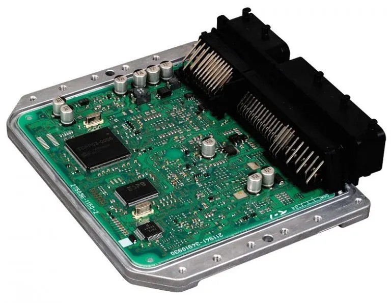
Inside the ECU, you’ll find microprocessors that process data from various sensors throughout your car. These sensors relay crucial information about engine temperature, speed, throttle position, and much more. The ECU uses this data to make real-time adjustments, ensuring the engine runs smoothly under diverse conditions. Modern ECUs are complex pieces of engineering, incorporating ceramic substrates, circuit boards, and reprogrammable microcontrollers.
There are primarily two types of ECUs:
- Digital ECUs: These utilize microprocessors to regulate current flow, offering precise control and advanced functionalities.
- Analog ECUs: Older systems rely on resistors and capacitors to manage current flow.
If you’re unsure about the type of ECU in your vehicle, consult your car’s service manual or contact the manufacturer. Knowing this detail can be helpful for more advanced diagnostics.
One fundamental way to begin ECU troubleshooting is by verifying power delivery. This is where a multimeter becomes invaluable. By connecting a multimeter to the ECU, you can check if it’s receiving the necessary voltage to operate correctly. If you are new to using a multimeter, don’t worry, we’ll guide you through the process.
How Engine Control Units Function: The Inner Workings
The ECU’s primary function is to optimize engine performance by precisely controlling the air-fuel mixture and ignition timing. It achieves this by constantly analyzing a stream of data from various sensors positioned throughout the vehicle. Think of it as a continuous feedback loop where sensor data informs ECU actions, resulting in optimized engine operation.
Here are some key sensor inputs that the ECU monitors:
- Engine Speed (RPM): Indicates how fast the engine crankshaft is rotating.
- Throttle Position: Reflects how much the accelerator pedal is pressed, indicating driver demand for power.
- Manifold Absolute Pressure (MAP): Measures the air pressure in the intake manifold, crucial for determining air density.
- Intake Air Temperature: Monitors the temperature of the air entering the engine, affecting air density and combustion efficiency.
- Oxygen Sensor Signal: Measures the oxygen content in the exhaust, allowing the ECU to fine-tune the fuel mixture for optimal combustion and emissions.
- Knock Sensor Signal: Detects engine knocking or pinging, enabling the ECU to adjust ignition timing to prevent engine damage.
Based on this sensor data, the ECU calculates the ideal air-fuel ratio and ignition timing. It then sends signals to control the fuel injectors and ignition system, ensuring the correct amount of fuel is injected and the spark plugs fire at the precise moment. Beyond these core functions, the ECU also manages other engine parameters and interacts with other vehicle systems. A malfunctioning ECU can disrupt this delicate balance, leading to various engine performance and drivability issues.
The Multimeter: Your Essential Diagnostic Tool
What is a Multimeter and Why You Need One
A multimeter is an electronic measuring instrument that combines several measurement functions in one unit. As the name suggests, it’s capable of measuring multiple electrical quantities, primarily voltage, current (amperage), and resistance (ohms). For automotive diagnostics, and specifically for testing your car ECU, a multimeter is an indispensable tool.
Every multimeter consists of three basic parts:
- The Dial (Selector Switch): This allows you to select the type of measurement (voltage, current, resistance) and the measurement range.
- The Probes (Leads): These are used to connect the multimeter to the circuit or component being tested. Typically, they are color-coded red (positive) and black (negative/ground).
- The Meter (Display): This displays the measured value. Multimeters can be either digital (displaying readings as numbers) or analog (using a needle to indicate readings on a scale). Digital multimeters are generally preferred for automotive work due to their accuracy and ease of reading.
Some advanced multimeters also offer additional features like capacitance measurement and frequency detection, which can be useful for more in-depth electronics troubleshooting. Multimeters are widely available at electronics stores and online retailers, ranging from basic models to professional-grade instruments. For basic ECU testing, a standard digital multimeter will suffice.
Step-by-Step Guide: How to Test ECU with a Multimeter
If you’re wondering how to test ECU with a multimeter, you’ve come to the right place. This section provides a detailed, step-by-step guide to help you through the process. A multimeter allows you to analyze the ECU’s power supply, ground connections, and signal inputs/outputs, helping you pinpoint potential issues.
Before you begin, it’s important to understand the basic electrical connections of an ECU:
- Power Supply: Provides the necessary voltage for the ECU to operate.
- Ground: Completes the electrical circuit, allowing current to flow. The ground is the reference point for voltage measurements.
- Signal Inputs/Outputs: These are the communication lines between the ECU and various sensors and actuators throughout the vehicle.
Here’s a step-by-step approach to testing your ECU with a multimeter:
Step 1: Safety First and Preparation
- Turn Off the Ignition: Completely turn off your car’s ignition and remove the ignition key. This is crucial for safety and prevents accidental electrical shorts.
- Locate the ECU: The ECU’s location varies depending on the car model, but it’s often found in the engine bay, under the dashboard, or sometimes under a seat. Consult your car’s repair manual for the exact location.
- Identify ECU Connectors: Examine the ECU. You’ll typically find one or two large connectors plugged into it. These connectors house the wires for power, ground, and signals.
- Access Wiring Diagrams: A wiring diagram for your specific car model is invaluable. It will show you the pinout of the ECU connectors, identifying which pins are for power, ground, and specific sensor/actuator signals. You can usually find these diagrams in a repair manual or online databases.
Step 2: Testing ECU Power Supply
- Set Multimeter to DC Voltage: Turn on your multimeter and set the dial to measure DC voltage (usually indicated by “VDC” or “DCV”). Select a voltage range that is higher than your car’s battery voltage (e.g., 20V DC range).
- Connect Multimeter Probes: Connect the black probe of your multimeter to a known good ground point on the vehicle’s chassis or the negative battery terminal. Connect the red probe to the ECU power supply pin, as identified in your wiring diagram.
- Check Voltage Reading: Turn the ignition key to the “ON” position (but do not start the engine). Observe the voltage reading on the multimeter. You should typically see a reading close to your car’s battery voltage, usually between 12 to 14 volts.
- Interpret Results:
- Correct Voltage (12-14V): Indicates the ECU is receiving power. Proceed to test ground and signals.
- Low or No Voltage: Suggests a problem in the power supply circuit, such as a blown fuse, a broken wire, or a faulty relay. Investigate the power supply circuit before proceeding further with ECU testing.
Step 3: Testing ECU Ground
- Set Multimeter to Continuity or Resistance: Turn off the ignition. Set your multimeter to measure continuity (usually indicated by a speaker symbol or a diode symbol) or low resistance (Ohms range). Continuity testing is preferable as it gives an audible beep when a connection is good.
- Connect Multimeter Probes: Connect one probe of the multimeter to a known good ground point on the vehicle’s chassis. Connect the other probe to the ECU ground pin, as identified in your wiring diagram.
- Check for Continuity or Low Resistance:
- Continuity Test: If your multimeter has a continuity function, it should beep, or the display should indicate continuity (often with a near-zero Ohm reading).
- Resistance Test: If using resistance mode, you should see a very low resistance reading (close to 0 Ohms).
- Interpret Results:
- Continuity or Low Resistance: Indicates a good ground connection.
- No Continuity or High Resistance: Suggests a problem with the ground connection, such as a loose connection, corrosion, or a broken ground wire. A poor ground can cause various ECU malfunctions.
Step 4: Testing ECU Signal Inputs and Outputs (Advanced)
Testing signal inputs and outputs is more complex and requires a deeper understanding of your car’s specific system and ECU wiring diagram. You’ll need to identify the pins for specific sensors and actuators you want to test.
- Identify Signal Pins: Using your wiring diagram, identify the pins corresponding to the sensor or actuator signals you want to test (e.g., throttle position sensor signal, oxygen sensor signal).
- Set Multimeter Appropriately: The appropriate multimeter setting (voltage, resistance, or frequency) will depend on the type of signal you are testing. Refer to your repair manual or wiring diagrams for signal specifications.
- Back-Probe Connections: Carefully back-probe the ECU connector pins. Back-probing involves inserting the multimeter probe into the back of the connector, alongside the wire, without disconnecting the connector from the ECU. This allows you to measure signals while the ECU is still connected and operating (if needed).
- Measure Signal Values: With the ignition ON or engine running (as required for the specific signal you are testing), measure the signal value with your multimeter.
- Compare to Specifications: Compare your measured signal values to the expected values specified in your car’s repair manual or wiring diagrams. Signal values can be voltages, resistances, frequencies, or pulse widths, depending on the sensor/actuator type.
- Interpret Results: Deviations from expected signal values can indicate problems with the sensor, actuator, wiring, or potentially the ECU itself.
Important Notes on ECU Testing:
- Wiring Diagrams are Essential: Never attempt to test ECU signals without accurate wiring diagrams for your specific car model. Incorrect probing can damage the ECU or other components.
- Back-Probing Technique: Use proper back-probing techniques to avoid damaging connector terminals or wires.
- Safety Precautions: Always disconnect the ignition and follow safety procedures when working with automotive electrical systems.
- Limitations of Multimeter Testing: Multimeter testing primarily checks for basic electrical continuity, voltage levels, and resistance. It may not detect all types of ECU faults, especially internal processing errors. More advanced diagnostic tools like scan tools and oscilloscopes may be needed for comprehensive ECU diagnostics.
Recognizing Symptoms of a Faulty ECU
Even before you reach for your multimeter, your car might be giving you clues that point towards a potential ECU problem. Recognizing these symptoms can help you decide if ECU testing is necessary.
1. Unusual Engine Behavior:
Erratic or abnormal engine performance is a common indicator of ECU issues. This can manifest in various ways:
- Reduced Engine Power: The engine may feel sluggish and lack its usual power, especially during acceleration.
- Poor Acceleration: The car may struggle to accelerate smoothly or quickly.
- Engine Stalling: The engine may stall unexpectedly, especially at idle or low speeds.
- Engine Misfiring: You might experience rough idling or a feeling of engine misfires, often accompanied by vibrations.
If you notice any of these engine performance problems, it’s wise to have a mechanic check the ECU and other engine components.
2. Check Engine Light Illumination:
The Check Engine Light (CEL) is a warning signal from your car’s onboard diagnostic system. While many issues can trigger the CEL, a constantly illuminated CEL can be a sign of a malfunctioning ECU. The ECU is responsible for monitoring various engine and emissions systems, and if it detects a problem within itself or related systems, it can activate the CEL. However, a CEL alone is not conclusive evidence of an ECU fault; it requires further investigation with a scan tool to read diagnostic trouble codes (DTCs).
3. Increased Emissions:
A failing ECU can disrupt the engine’s air-fuel mixture and combustion process, leading to increased emissions. You might notice:
- Failing Emissions Tests: Your car may fail emissions tests due to high levels of pollutants.
- Excessive Exhaust Smoke: You might observe more smoke than usual coming from the exhaust pipe, potentially with an unusual color or odor.
Increased emissions are not only environmentally unfriendly but can also indicate a problem with the ECU’s control over the engine’s combustion process.
FAQs About ECU Testing
Question 1: How else can I test the ECU besides using a multimeter?
Answer: While a multimeter is excellent for basic electrical checks, other methods exist for more comprehensive ECU testing. Bench testing involves simulating car electrical systems and sensors on a test bench to evaluate the ECU’s functionality outside the vehicle. ECU simulators and diagnostic scanners are software tools that allow you to communicate with the ECU, monitor parameters, read fault codes, and analyze outputs, providing deeper insights into ECU operation.
Question 2: What are the risks if I don’t test the ECU properly?
Answer: Improper ECU testing can lead to several risks. You could damage the ECU itself through incorrect probing or applying excessive voltage. This might necessitate costly repairs or ECU replacement. Furthermore, improper testing can lead to misdiagnosis, causing you to replace other components unnecessarily while the actual problem remains unresolved. In some cases, improper electrical work can even void your car’s warranty. Always follow proper procedures and use wiring diagrams to minimize these risks.
Question 3: Can ECU faults be prevented?
Answer: While ECUs are designed to be durable, preventative maintenance can help minimize the risk of faults. Regular car servicing and adhering to recommended maintenance schedules are crucial. Ensure your car has adequate oil and coolant levels to prevent engine overheating, which can indirectly stress the ECU. Regularly testing your car battery and ensuring a stable power supply can also benefit the ECU. Checking engine mounts and maintaining proper brake fluid levels, as mentioned in some contexts, are less directly related to ECU health but contribute to overall vehicle maintenance, which indirectly supports the longevity of all components.
Question 4: What happens if ECU fuses are faulty?
Answer: A blown ECU fuse is a common cause of ECU malfunction and is often simpler to resolve than internal ECU damage. A blown fuse can prevent the engine from starting or cause the car to stall. If you suspect an ECU fuse issue, first disconnect the battery terminals to prevent short circuits during fuse replacement. Locate the fuse box (usually under the dashboard or in the engine bay), identify the ECU fuse (refer to the fuse box diagram), and inspect it for damage. If the fuse is blown (the internal wire is broken), replace it with a fuse of the same amperage rating. If the fuse blows again immediately after replacement, it indicates a more serious electrical fault that needs professional diagnosis.
Wrapping Up: Empowering Your Car Diagnostics
Understanding how to test your car ECU with a multimeter is a valuable skill for any car owner or DIY enthusiast. While it’s not a complete diagnostic solution, multimeter testing allows you to perform essential checks on ECU power supply and ground connections, helping you rule out basic electrical issues. If you suspect ECU problems based on symptoms or multimeter readings, it’s always recommended to consult a qualified automotive technician for further diagnosis and repair.
This guide has provided you with a comprehensive overview of ECU testing with a multimeter. By understanding the ECU’s function, multimeter basics, and the step-by-step testing process, you’re now better equipped to troubleshoot potential ECU-related issues in your vehicle. Have you tried testing your ECU with a multimeter? Share your experiences and questions in the comments below!
Related Articles
How to Test ECU with Multimeter: Complete Guide
Multimeter Not Reading Current [How to Fix]
Multimeter Not Reading DC Voltage: How to Fix it?