
The Engine Control Unit (ECU), often also referred to as the Powertrain Control Module (PCM) or Engine Control Module (ECM), is the brain of your modern vehicle. It manages everything from engine performance and fuel efficiency to emissions control and transmission operation. When your scan tool displays a “Car Ecu Not Communicating” message, it indicates a serious problem that prevents you from diagnosing and potentially repairing various car issues. This lack of communication can stem from a range of issues, from simple glitches to complex electrical faults.
This guide provides a systematic approach to diagnosing why your car’s ECU is not communicating, helping you pinpoint the problem and get your vehicle back on the road. We’ll cover preliminary checks and delve into wiring troubleshooting, focusing on power, ground, and communication circuits.
I. Preliminary Checks: Ruling Out the Obvious
Before diving into complex wiring diagnostics, it’s crucial to perform some basic preliminary checks. These steps can often save you time and effort by identifying simple causes or eliminating potential misdiagnoses.
1. Scan for Communication Related U-Codes in Other Modules
When you encounter a “no communication” error with a specific module, such as the Anti-lock Braking System (ABS) module, your first step should be to perform a full vehicle scan. This means attempting to communicate with all other available electronic control units in the car.
Modern vehicles are equipped with multiple interconnected ECUs that communicate with each other over data networks. If one ECU loses communication, others may detect this and store Diagnostic Trouble Codes (DTCs) related to communication loss. These codes often start with the letter “U,” for example, U0121, which signifies “Lost Communication with ABS Module.”
- If U-codes are present in other modules: This strongly suggests a genuine communication problem. The presence of U-codes in other ECUs corroborates that the module you are initially trying to communicate with (e.g., ABS module) is indeed experiencing a communication issue. Proceed with wiring troubleshooting as outlined in the next sections.
- If no U-codes are present: While the absence of U-codes doesn’t definitively rule out a communication problem, it prompts further investigation.
- Try a different scan tool: “No communication” messages can sometimes be due to scan tool issues, either software or hardware related. Attempting communication with a different, known-good scan tool is a vital step. A different scan tool might successfully connect, indicating the initial problem was with your tool, not the car’s ECU.
- Remember limitations: Be aware that not all vehicles and ECU configurations will trigger U-codes in other modules when one ECU is offline. The absence of U-codes doesn’t guarantee the communication system is flawless; it simply means other modules haven’t explicitly reported a loss of communication in the form of a U-code. Treat the absence of U-codes with caution and continue systematic diagnostics if the problem persists.
2. Verify Scan Tool Functionality
It’s essential to ensure your scan tool is functioning correctly and is compatible with the vehicle you are diagnosing.
- Check scan tool compatibility: Confirm that your scan tool supports the make, model, and year of the vehicle you are working on. Some scan tools have limited vehicle coverage.
- Software updates: Ensure your scan tool software is up to date. Outdated software can sometimes cause communication issues with newer vehicles.
- Scan tool cable and connections: Inspect the scan tool cable and OBDII connector for any damage or bent pins. A poor connection can lead to communication failure. Try wiggling the cable at both ends (scan tool and OBDII port) to see if communication is intermittent.
- Power to scan tool: If your scan tool is battery-powered, ensure it is adequately charged. Some scan tools rely on power from the vehicle’s OBDII port; ensure the vehicle’s OBDII port is providing power (check vehicle’s fuse if necessary, although OBDII port power issues are rare).
By completing these preliminary checks, you can eliminate common causes of “car ECU not communicating” errors and focus your troubleshooting efforts more effectively.
II. Deep Dive into Wiring Troubleshooting
If preliminary checks haven’t resolved the “car ECU not communicating” issue, the next step is to systematically troubleshoot the ECU’s wiring. This involves examining the essential electrical circuits that enable the ECU to function and communicate: power supply, ground, and communication wires.
1. Obtain Detailed Wiring Diagrams
The cornerstone of effective wiring troubleshooting is access to accurate and detailed wiring diagrams for the specific vehicle and ECU you are diagnosing. Wiring diagrams illustrate the electrical circuits, components, and pinouts for the ECU, providing a roadmap for your diagnostic process.
- Vehicle-specific diagrams: Generic wiring diagrams are often insufficient. Obtain diagrams specifically for the make, model, year, and engine type of the vehicle you are working on. Online subscription services, vehicle manufacturer websites, or repair information databases are valuable resources for acquiring these diagrams.
- Module-specific diagrams: Focus on the wiring diagram relevant to the ECU you are having communication problems with (e.g., ECM, PCM, ABS module).
- Understanding diagram symbols: Familiarize yourself with the symbols and conventions used in automotive wiring diagrams. These diagrams typically depict wires, connectors, fuses, relays, ground points, and components, along with wire colors and circuit identifications.
While wiring diagrams vary across vehicle models and ECUs, all ECUs share fundamental wiring requirements for proper operation. For a typical Engine Control Module (ECM), the essential circuits to investigate for “car ECU not communicating” issues are:
2. Power Supply Checks
ECUs require a stable and sufficient power supply to operate. A lack of power is a common cause of communication failure. ECUs typically rely on multiple power inputs:
- Constant Battery Power (B+): This provides continuous power to the ECU, even when the ignition is off. It’s crucial for maintaining ECU memory and certain background functions.
- Ignition Switch Power (IGN): This power supply is activated when the ignition switch is turned to the “ON” or “RUN” position. It powers up the ECU’s main processing functions during vehicle operation.
- Main Relay (EFI Relay, DME Relay): Many ECUs, particularly ECMs, utilize a “main relay” (also known as EFI relay or DME relay in some vehicles). This relay, often controlled by the ECU itself, provides power to various sensors, actuators, and sometimes directly to the ECU. The main relay circuit ensures that power is supplied to critical engine management components only when the ECU is active.
Testing Power Supplies:
- Locate ECU power pins: Refer to your wiring diagram to identify the pins on the ECU connector that correspond to constant battery power, ignition power, and main relay power (if applicable).
- Voltage testing: Use a digital multimeter to measure the voltage at each power pin with respect to a known good ground.
- Constant Battery Power: Should measure battery voltage (approximately 12.6V with the engine off). Test with the ignition OFF.
- Ignition Switch Power: Should measure battery voltage when the ignition is switched ON and 0V when OFF.
- Main Relay Power: Should measure battery voltage when the ignition is ON and the main relay is activated. You may need to check both the input and output sides of the relay.
- Test under load: Voltage readings alone can be misleading. A wire may show voltage but be unable to carry current due to corrosion or internal strand breakage. Always test power circuits under load.
- Test light method: Use a test light connected to ground and probe the power supply pins. A dim or non-illuminating test light under load indicates a voltage drop or insufficient current flow.
- Headlight bulb method: For a more substantial load test, use a headlight bulb connected in series with the power circuit. A dim headlight bulb indicates a problem.
If any power supply circuit exhibits low voltage or fails under load, trace the circuit back towards the power source (battery, ignition switch, main relay, fuses) to identify the point of failure (e.g., blown fuse, corroded connector, wiring break).
3. Ground Circuit Checks
Just as crucial as power supply is a solid and reliable ground connection for the ECU. ECUs rely on ground circuits to complete electrical paths and establish a common voltage reference. Poor or missing ground connections are frequent culprits in “car ECU not communicating” scenarios.
Testing Ground Circuits:
- Locate ECU ground pins: Consult your wiring diagram to identify the ground pins on the ECU connector. ECUs often have multiple ground pins.
- Continuity testing: Use a digital multimeter in continuity mode to check for continuity between the ECU ground pins and a known good chassis ground point. You should measure near 0 ohms resistance, indicating a good ground connection.
- Voltage drop testing under load: Similar to power circuits, ground circuits should also be tested under load.
- Voltage drop method: With the ECU connected and the ignition ON, measure the voltage drop between the ECU ground pin and a known good chassis ground point. A voltage drop exceeding 0.2-0.3V indicates excessive resistance in the ground circuit.
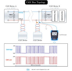
This image illustrates a typical CAN Bus topology, highlighting the importance of terminating resistors for proper communication. Terminating resistors are crucial components in a CAN Bus network that help prevent signal reflections and ensure reliable data transmission between ECUs.
If ground circuit testing reveals high resistance or voltage drop, inspect the ground wire, ground connection points (often bolted to the vehicle chassis or engine block), and connectors for corrosion, looseness, or damage. Clean and tighten ground connections as needed.
4. Communication Wiring Inspection
Modern vehicles utilize sophisticated communication networks to enable ECUs to exchange data. If the ECU’s communication wiring is faulty, it will be unable to communicate with scan tools or other modules. Common communication protocols in vehicles include:
- CAN Bus (Controller Area Network): A high-speed, two-wire communication protocol widely used in automotive applications.
- K-Line: A single-wire communication protocol, older and slower than CAN Bus, but still found in some vehicles, especially for diagnostic communication.
- LIN Bus (Local Interconnect Network): A lower-speed, single-wire protocol often used for communication with less critical components like window lift motors or steering wheel controls.
- MOST (Media Oriented Systems Transport): A fiber optic network used for high-bandwidth multimedia and infotainment systems in some luxury vehicles.
For “car ECU not communicating” issues, focus primarily on CAN Bus and K-Line, as these are most commonly used for diagnostic communication.
Inspecting Communication Wires:
- Locate communication wires: Refer to your wiring diagram to identify the communication wires for the ECU you are diagnosing. For CAN Bus, you’ll typically find CAN High and CAN Low wires. For K-Line, there will be a single K-Line wire.
- Visual inspection: Carefully inspect the communication wires and connectors for any signs of damage, such as cuts, abrasions, melted insulation, or corrosion. Pay close attention to areas where wiring harnesses are routed near sharp edges, moving parts, or heat sources.
- Continuity testing: With the ignition OFF and the ECU disconnected, use a digital multimeter to check for continuity in the communication wires from the ECU connector to the diagnostic connector (OBDII port) or other relevant modules as indicated by the wiring diagram.
- Short circuit testing: Check for short circuits to ground and power in the communication wires. With the ECU disconnected, measure the resistance between each communication wire and a known good ground, and between each communication wire and battery positive. You should measure very high resistance (open circuit) in both cases, indicating no short circuits.
- CAN Bus specific checks: For CAN Bus systems, additional checks are necessary:
- CAN Bus resistance: With the ignition OFF and battery disconnected, measure the resistance between the CAN High and CAN Low wires at the diagnostic connector (OBDII port). A properly terminated CAN Bus network should measure approximately 60 ohms. A reading of 120 ohms suggests a missing terminating resistor, while a reading significantly lower than 60 ohms may indicate a short circuit or additional terminating resistors.
This diagram illustrates the voltage levels of a CAN Bus signal. CAN High typically ranges from 2.5V to 3.5V, and CAN Low from 1.5V to 2.5V. The differential voltage between CAN High and CAN Low is used to transmit data. Understanding these voltage levels is crucial for advanced CAN Bus diagnostics.
- **Differential voltage testing:** With the ignition ON and the ECU connected, use a voltmeter or oscilloscope to measure the voltage on the CAN High and CAN Low wires. CAN High should typically be around 2.5V to 3.5V, and CAN Low around 1.5V to 2.5V. More advanced diagnostics with an oscilloscope can reveal signal integrity issues, such as signal clipping, noise, or reflections.By systematically checking power, ground, and communication wiring, you can effectively diagnose many “car ECU not communicating” problems. Remember to always consult vehicle-specific wiring diagrams and perform tests methodically. If wiring issues are ruled out, the ECU itself may be faulty and require replacement or professional repair.
If you have further questions or encounter complex scenarios, consulting a qualified automotive technician is recommended.