Car maintenance and diagnostics are becoming increasingly reliant on electronic systems. For enthusiasts and professionals alike, tasks like ECU programming, module updates, and even detailed diagnostics often require a stable and reliable power supply. Low voltage during these procedures can lead to frustrating errors and even damage to sensitive electronic components, as highlighted by common issues like FRM module failures in certain vehicle models. While commercial car programming power supplies like the MST-80 or Schumacher INC-700A are available, their high price tags, ranging from $300 to $700, can be a significant barrier. Fortunately, a cost-effective and powerful alternative exists: repurposing server-grade power supplies.
This guide demonstrates how to build your own Car Programming Power Supply using a server power supply, offering a budget-friendly solution without compromising on performance. This DIY approach provides several key advantages:
- Cost-Effective: Significantly cheaper than dedicated automotive power supplies.
- High Amperage Output: Provides ample power for demanding car programming tasks.
- Efficient Performance: Server power supplies are designed for high efficiency and reliability.
Let’s dive into the steps to create your own robust car programming power supply.
Transforming a Server Power Supply into a Car Programming Powerhouse
This project utilizes the HP DPS-1200FB A HSTNS-PD11 server power supply as a base due to its availability and excellent specifications. Here’s what you’ll need to gather for this DIY car programming power supply build:
Hardware Components:
- HP DPS-1200FB Server Power Supply (HSTNS-PD11): Easily sourced online from marketplaces like eBay or Kijiji. (~$40)
- LCD Digital Display Multimeter (6.5-100V, 0-100A): For monitoring voltage and current output. Available on Amazon and similar retailers. (https://www.amazon.ca/gp/product/B01K75Q4MU/ref=ppx_yo_dt_b_asin_title_o00_s01) (~$25)
- Round Rocker Switch: For convenient on/off control of the 14V output. (~$5)
- 8AWG Booster Cables: To provide robust power delivery to your car. (https://www.canadiantire.ca/en/pdp/motomaster-booster-cables-10-ft-8-gauge-0111212p.html) (~$16)
- 8AWG Wire Lug Ring Clamps: For secure connections to the power supply and battery terminals. (~$5 per pair)
- 22k Resistor: To enable the power supply output.
- 82k Resistor & 18k Resistor: To adjust voltage regulation and overcome over-voltage protection. (Alternatively, close values like 75k and 15k can be used if readily available).
- Project Enclosure (Optional): An old case, like from an electric stapler, or any suitable box to house the components safely.
- Solid Core Wire (Various Colors): For internal wiring.
- Zip Ties: For cable management and securing components.
- Solder & Soldering Iron: For making electrical connections.
- Electrical Tape or Kapton Tape: For insulation.
Tools:
- Screwdrivers
- Wire Strippers/Cutters
- Drill (for mounting switch and fan hole if using an enclosure)
Total Estimated Hardware Cost: ~$91
This project offers a significant cost saving compared to commercial car programming power supplies, while delivering comparable or even superior performance.
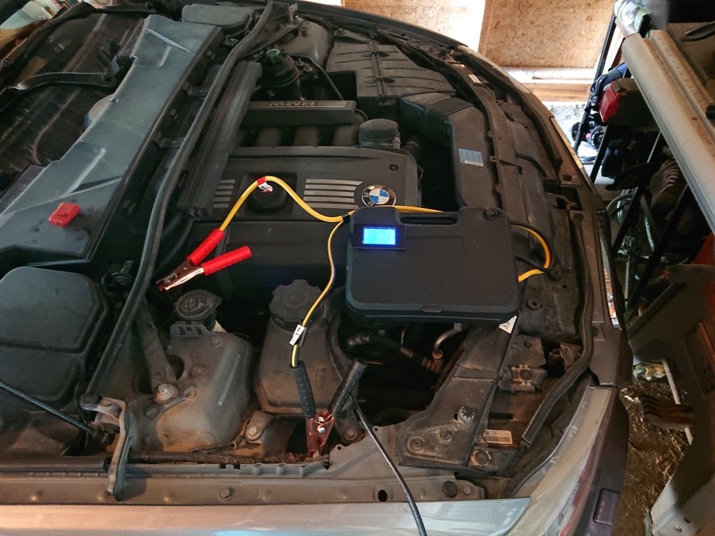
Image: The completed DIY car programming power supply connected to a vehicle, showcasing the digital multimeter displaying voltage and amperage during operation.
Step-by-Step Guide to Building Your DIY Power Supply
Follow these steps to convert your server power supply into a reliable car programming power supply. Remember to exercise caution when working with electronics and mains power.
1. Enable Power Supply Output:
To activate the HP DPS-1200FB, you need to apply a resistor between specific pins. Solder a 22k resistor between pins 33 and 32 on the power supply. This step is crucial to turn on the power supply.
Image: Detailed view of the 22k resistor soldered between pin 33 and 32 on the power supply, illustrating the connection point for enabling the output.
2. Modify Voltage Regulation for 14V Output:
Open the power supply casing carefully. Locate the edge circuit board, which controls voltage adjustment and monitoring. To achieve the desired 14V output for car programming, we need to modify the voltage regulation circuitry.
Image: Overview of the server power supply with the top cover removed, indicating the position of the edge circuit board that needs modification.
By default, the power supply’s potentiometer (pot) won’t allow adjustment high enough for 14V, and the Over Voltage Protection (OVP) will prevent setting this output. To overcome this, solder an 82k resistor and an 18k resistor in specific locations on the board. These resistor values modify the regulation circuit to allow for a 14V setting. If 82k and 18k are not available, 75k and 15k resistors provide a close alternative.
Important: Insulate the resistors from the circuit board using electrical tape or Kapton tape to prevent short circuits.
Image: Illustration of the original circuit board layout before modification, highlighting the components involved in voltage regulation adjustment.
Image: Close-up of the 82k resistor soldered onto the circuit board, demonstrating the modification for voltage regulation tuning.
Image: Detail of the 18k resistor soldered onto the circuit board, working in conjunction with the 82k resistor to enable 14V output.
3. Adjust Voltage Output:
After installing the resistors, adjust the potentiometer on the circuit board to set your desired output voltage. Aim for 14.2V initially, as the voltage will slightly drop when amperage draw increases under load. Use your multimeter to accurately monitor the voltage during adjustment.
Image: Adjusting the potentiometer on the modified circuit board to achieve the target 14.2V output for optimal car programming conditions.
4. Wire the Output Cables and Switch:
Cut a suitable length (e.g., 1 meter) of 8AWG booster cable to create your output leads. Solder wire lug ring clamps to one end of each cable for connecting to the power supply output terminals and attach clamps to the other ends for car battery connection.
Wire the SPST rocker switch to control the 14V output. The switch should complete the circuit between pin 36 and ground to turn the 14V output on or off. This provides a safe and convenient way to enable/disable the car programming power supply.
5. Assemble and Enclose (Optional):
Mount the LCD multimeter, rocker switch, and wiring within your chosen enclosure if using one. Secure the internal circuitry using zip ties for cable management and strain relief. Ensure proper ventilation, especially for the power supply fan. Cut a hole for the fan to vent hot air effectively, preventing overheating during extended use.
Image: The 100A shunt integrated into the power supply setup, allowing for accurate current measurement and monitoring during car programming.
Image: Internal view of the power supply enclosure’s top section, demonstrating organized wiring and placement of electronic components for a clean build.
Image: Side profile of the assembled power supply enclosure, highlighting the fan ventilation hole for heat dissipation and cooling.
Usage and Safety Guidelines for Your DIY Car Programming Power Supply
- Crucial Safety Step: ALWAYS TURN ON THE POWER SUPPLY BEFORE CONNECTING IT TO YOUR CAR. This prevents potential issues related to reverse current.
- No Reverse Path Protection: This DIY power supply is not designed to protect against reverse current from the car battery.
- No Short Circuit Fuse: The power supply is not fused for short circuit protection. Exercise extreme caution to avoid short circuits.
- Fan Operation: The power supply fan will continue to run as long as the power supply is plugged into the mains, even when the 14V output is switched off. This is normal.
- Discharge Time: Allow approximately 20 seconds for the power supply to fully de-energize after being switched off. The capacitors need time to discharge. Do not touch the clamps together or place them down immediately after switching off until the voltmeter reading confirms safe discharge.
Image: Power supply in the off state with no load, indicating the voltage reading on the multimeter prior to connecting to a vehicle.
Image: Power supply in the on state but unloaded, displaying the voltage on the multimeter in preparation for car programming tasks.
Image: Close-up of the LCD multimeter display, showing the voltage reading of the DIY car programming power supply while in the ‘on’ and unloaded condition.
By following these instructions and safety guidelines, you can create a powerful and affordable car programming power supply for your automotive projects, saving you significant costs compared to commercial alternatives. This DIY project provides a reliable power source for successful ECU programming, diagnostics, and module updates, ensuring stable voltage and ample amperage for your vehicle’s electronic needs.