Electronic Control Units (ECUs) are the brains of modern vehicles, managing everything from engine performance to safety systems. For anyone involved in car repair or diagnostics, a solid understanding of ECUs is essential. This guide provides a comprehensive introduction to ECUs in cars, their functions, and their critical role in vehicle systems.
What is an ECU in a Car?
Imagine the human brain – that’s essentially what an ECU is for your car. ECU stands for Electronic Control Unit, and it’s a generic term for any embedded system that controls one or more of the electrical systems or subsystems in a vehicle. Think of them as mini-computers distributed throughout your car, each responsible for specific tasks and communicating with each other to ensure smooth operation.
To visualize this, consider your car’s systems as parts of a body:
- The ECUs are like individual organs, each with a specific function (engine control, braking, etc.).
- The CAN bus acts as the nervous system, allowing these organs (ECUs) to communicate and coordinate.
Physically, ECUs are interconnected via a network, typically using a two-wire system known as the CAN (Controller Area Network) bus. This bus consists of a twisted pair of wires, CAN high and CAN low, often color-coded yellow (high) and green (low).
Alt text: Diagram illustrating the CAN bus system in a modern car, highlighting the interconnected Electronic Control Units (ECUs) and the communication network.
Alt text: Close-up of a CAN bus wiring harness showing the twisted pair wires in yellow (CAN high) and green (CAN low), used for ECU communication.
Alt text: Conceptual diagram of ECU network communication on a CAN bus, demonstrating how ECUs send, accept, and reject messages for efficient data sharing.
Decoding the ECU: Core Components
Each ECU is a sophisticated piece of technology, comprised of three main components that work in harmony:
- Microcontroller (MCU): This is the “brain” of the ECU. The MCU processes information, executes instructions, and makes decisions based on the data it receives. It interprets incoming CAN messages and determines which messages the ECU should transmit. For example, in an engine ECU, the MCU manages fuel injection timing and ignition based on sensor inputs.
- CAN Controller: Integrated within the MCU, the CAN controller manages the complexities of CAN communication. It handles message encoding, error detection, and arbitration, ensuring that all communication adheres to the CAN protocol. This offloads the communication burden from the MCU, allowing it to focus on control tasks.
- CAN Transceiver: This component acts as the interface between the CAN controller and the physical CAN bus wires. It converts the digital data from the controller into differential signals suitable for transmission over the CAN bus and vice versa. The transceiver also provides crucial electrical protection for the ECU.
Alt text: Illustration of an Electronic Control Unit (ECU) as a CAN bus node, showing the microcontroller, CAN controller, and CAN transceiver components.
Alt text: Diagram of a CAN bus DB9 connector pinout, detailing the pin assignments for CAN high, CAN low, ground, and other signals commonly used in CAN bus interfaces.
Connecting to the ECU Network: CAN bus Connectors
Connecting to a car’s CAN bus network is essential for diagnostics, data logging, and ECU programming. While there isn’t a single, universal connector for all CAN bus applications in vehicles, the DB9 (D-sub9) connector, as per CANopen CiA 303-1, is a widely adopted standard, particularly for CAN bus data loggers and interfaces. However, be aware that different vehicle manufacturers and models may utilize various connector types, requiring different adapter cables for accessing the CAN bus.
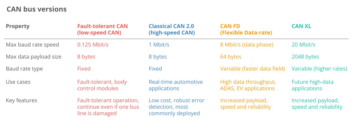
Varieties of CAN Bus in Automotive Systems
The CAN bus technology has evolved, leading to several variants designed for different needs and performance levels within automotive and other applications:
- Low-Speed CAN (Fault-Tolerant CAN): This variant prioritizes reliability in harsh environments where fault tolerance is critical. While robust, it operates at lower speeds and is increasingly being replaced by LIN (Local Interconnect Network) bus for less critical applications.
- High-Speed CAN (Classical CAN): The most prevalent CAN variant in vehicles today. It strikes a balance between speed and reliability, suitable for a wide range of automotive control and communication tasks. This is the primary focus of this article.
- CAN FD (Flexible Data-Rate): An evolution of Classical CAN, CAN FD offers significantly faster data rates and larger data payloads. This makes it suitable for applications demanding higher bandwidth, although its adoption is still growing. You can delve deeper into this in our CAN FD introduction.
- CAN XL (eXtra Large): The latest CAN innovation, CAN XL, pushes the boundaries further with even greater data rates and payload capacities, aiming to bridge the gap between CAN and Automotive Ethernet for future vehicle architectures.
Beyond CAN, modern vehicles often incorporate other communication networks:
- LIN Bus: A cost-effective complement to CAN bus, LIN is used for less demanding applications like window lifts, mirrors, and climate control. It simplifies wiring and reduces node cost. Learn more in our LIN bus intro.
- FlexRay: Offering higher speeds than CAN and fault tolerance through redundancy, FlexRay is used in safety-critical systems requiring deterministic communication. However, it’s more complex and expensive than CAN.
- Automotive Ethernet: Increasingly adopted for high-bandwidth applications like advanced driver-assistance systems (ADAS), infotainment, and cameras. Automotive Ethernet provides much faster data transfer rates but differs from CAN in its safety and real-time performance characteristics. The future of automotive networking will likely involve a combination of Automotive Ethernet, CAN FD, and CAN XL.
Key Advantages of CAN Bus and ECUs in Automotive Applications
The widespread adoption of CAN bus and ECU-based systems in vehicles is driven by several compelling benefits:
Alt text: Graphic highlighting the low cost and simplicity benefits of CAN bus systems in automotive applications, emphasizing reduced wiring and complexity.
1. Simplicity and Cost-Effectiveness
Replacing complex point-to-point wiring with a single CAN bus network dramatically reduces wiring complexity, weight, and overall system cost.
- Reduced Wiring: Traditional wiring systems required dedicated wires between each component, leading to bulky, expensive, and inflexible harnesses. CAN bus uses a shared two-wire system, significantly simplifying wiring. Think of the difference between NMEA 0183 and the streamlined NMEA 2000 NMEA 2000 vs. NMEA 0183.
- Weight Reduction: By minimizing wiring, CAN bus systems contribute to significant weight savings in vehicles. This can reduce the weight of a car’s wiring harness by up to 20 kg, improving fuel efficiency.
- Economies of Scale: The widespread use of CAN bus has created a large market, driving down the costs of components like controllers, transceivers, and associated tools, making it a highly cost-effective solution.
Alt text: Illustration emphasizing the centralized nature of CAN bus networks, enabling easy access for diagnostics, data logging, and ECU configuration from a single point.
2. Enhanced Accessibility and Diagnostics
CAN bus provides a central access point to all ECUs in the network, simplifying diagnostics, data logging, and ECU programming.
- Centralized Diagnostics: Connecting to the CAN bus at any point allows access to communication from all ECUs. This streamlines diagnostics, eliminating the need to individually access each ECU.
- Silent CAN Logging: CAN bus data logging can be performed passively without disrupting the network, crucial for accurate diagnostics and troubleshooting.
- ECU Flashing and Updates: Firmware and configuration updates can be transmitted as CAN frames, allowing for remote ECU reprogramming via higher-layer protocols like UDS or CCP/XCP.
- Standardization and Interoperability: Standardized higher-layer protocols built on CAN bus enhance the compatibility of diagnostic tools and software across different manufacturers and vehicle models.
Alt text: Graphic depicting the robustness of CAN bus against electromagnetic interference (EMI), highlighting its suitability for safety-critical automotive applications.
3. Exceptional Robustness and Reliability
CAN bus is designed to operate reliably in electrically noisy environments and is highly resilient to disturbances, making it ideal for safety-critical automotive applications.
- Differential Signaling: CAN bus uses differential signaling, where data is transmitted as the voltage difference between two wires. Electromagnetic interference affects both wires equally, preserving the signal difference and making the communication robust against noise.
- Comprehensive Error Handling: CAN incorporates sophisticated error detection mechanisms, including bit errors, stuff errors, CRC errors, form errors, and ACK errors. Faulty messages are automatically retransmitted, ensuring data integrity.
- Error Confinement: CAN nodes monitor their own error counts and can disconnect themselves from the bus if errors exceed a threshold. This “bus off” mechanism prevents faulty nodes from disrupting the entire network.
Alt text: Diagram illustrating the efficient priority-based arbitration of CAN bus, ensuring high-priority messages get immediate access and optimizing bandwidth utilization.
4. Efficient Communication and Prioritization
CAN bus prioritizes messages based on their ID, ensuring critical data gets immediate bus access without interrupting other communications.
- Message Arbitration: When multiple ECUs attempt to transmit simultaneously, the CAN bus uses a non-destructive bitwise arbitration process. The message with the lowest CAN ID (highest priority) wins bus access, while others back off and retry.
- Optimized Bandwidth Utilization: Arbitration ensures efficient use of bus bandwidth, filling gaps between high-priority messages with lower-priority data, maximizing overall throughput.
- Sufficient Speed: While Classical CAN might be slower compared to technologies like Automotive Ethernet, it offers ample speed (up to 1 Mbit/s) for the majority of automotive and industrial control applications, enabling the transmission of thousands of CAN frames per second.
A Brief History of CAN Bus Development
- Pre-CAN Era: Vehicle ECUs relied on complex, point-to-point wiring systems.
- 1986: Bosch engineers developed the CAN protocol to address the increasing complexity of automotive electronics.
- 1991: Bosch released CAN 2.0, defining the standard CAN frame formats (CAN 2.0A: 11-bit ID, 2.0B: 29-bit ID).
- 1993: CAN became an international standard, ISO 11898, solidifying its place in the industry.
- 2003: ISO 11898 evolved into a series of standards, further refining CAN specifications.
- 2012: Bosch introduced CAN FD 1.0, enabling flexible data rates for increased bandwidth.
- 2015: CAN FD was standardized as ISO 11898-1, promoting wider adoption.
- 2016: The physical layer for CAN FD, ISO 11898-2, was standardized for data rates up to 5 Mbit/s (and practically up to 8 Mbit/s).
- 2018: CiA began development of CAN XL to meet future bandwidth demands.
- 2024: CAN XL was standardized (ISO 11898-1:2024, 11898-2:2024), paving the way for even faster CAN communication.
Today, CAN is the dominant communication standard in automobiles, trucks, buses, agricultural machinery, marine vessels, aircraft, electric vehicle batteries, industrial equipment, and more.
Alt text: Iconographic representation of diverse CAN bus applications, including buses, trucks, machinery, tractors, and automotive vehicles, showcasing its broad industry usage.
Alt text: Timeline infographic illustrating key milestones in CAN bus history from its inception in 1986 to recent developments, marking standardization and technological advancements.
Alt text: Visual representation of the future of CAN bus, highlighting its integration with connected vehicles, cloud computing, and the Internet of Things (IoT) for advanced automotive systems.
The Future Trajectory of CAN Bus Technology
CAN bus is expected to remain a vital technology in automotive and industrial sectors, although it will evolve to meet emerging demands:
- Demand for Higher Bandwidth: The increasing data volumes in vehicles, driven by ADAS and complex systems, will push the adoption of CAN FD, CAN XL, and Automotive Ethernet for higher data rates.
- Connected Vehicle Ecosystems: The rise of cloud connectivity and vehicle telematics will enable advanced functionalities like predictive maintenance and remote diagnostics. However, this connectivity also introduces cybersecurity concerns.
- Openness and Data Access: The trend towards ‘Open Source’ and ‘Right to Repair’ may contrast with OEMs’ desire to keep vehicle data proprietary for subscription-based services.
Despite the emergence of newer technologies, the transition from Classical CAN will likely be gradual. While CAN FD is gaining traction, Classical CAN remains dominant in on-road vehicles. Automotive Ethernet is crucial in OEM research and development, but its widespread impact on replacing Classical CAN in existing vehicle architectures is yet to be fully realized.
Download the Ultimate CAN Bus Guide in PDF Format
Want to become proficient in CAN bus technology?
Get our comprehensive collection of 12 ‘simple intros’ in a single, downloadable 160+ page PDF guide:
Download now
Deep Dive: CAN Bus Physical and Data Link Layers
From a technical perspective, CAN bus is defined by two layers within the OSI model: the physical layer and the data link layer. For high-speed CAN, ISO 11898-2 specifies the physical layer, while ISO 11898-1 defines the data link layer.
Alt text: Diagram illustrating the CAN bus within the 7-layer OSI model, pinpointing its operation at the Physical Layer (ISO 11898-2) and Data Link Layer (ISO 11898-1) for network communication.
Physical Layer (ISO 11898-2)
The physical layer defines the hardware aspects of CAN communication, including:
- Baud Rate: Specifies the data transmission rate, up to 1 Mbit/s for Classical CAN and 8 Mbit/s for CAN FD.
- Cable Type and Length: Defines cable specifications and maximum cable lengths, ranging from 500 meters at 125 kbit/s to 40 meters at 1 Mbit/s.
- Termination: Requires 120 Ohm termination resistors at each end of the CAN bus to prevent signal reflections.
Data Link Layer (ISO 11898-1)
The data link layer manages data framing, transmission, error handling, and ensures data integrity. Key aspects include:
- Frame Formats: Defines four frame types: data frames, remote frames, error frames, and overload frames, with 11-bit and 29-bit identifiers.
- Error Handling: Implements robust error detection and handling mechanisms, including CRC, acknowledgement slots, and error counters.
- Arbitration: Utilizes non-destructive bitwise arbitration based on message ID priority to manage bus access and prevent data collisions.
Understanding the CAN Frame Structure
Communication on the CAN bus happens through CAN frames. The standard CAN data frame with an 11-bit identifier (CAN 2.0A), commonly used in cars, is structured as follows (the 29-bit identifier frame, CAN 2.0B, used in protocols like J1939, has a similar structure with an extended ID):
Alt text: Detailed breakdown of a standard CAN bus frame structure, labeling each segment from Start of Frame (SOF) to End of Frame (EOF), including ID, Data, CRC, and ACK fields.
- SOF (Start of Frame): A dominant ‘0’ bit signaling the beginning of a CAN frame.
- ID (Identifier): An 11-bit identifier that determines message priority (lower ID = higher priority).
- RTR (Remote Transmission Request): Indicates whether the frame is sending data or requesting data (dominant ‘0’ for data, recessive ‘1’ for request).
- Control: Contains IDE (Identifier Extension Bit, ‘0’ for 11-bit IDs) and DLC (Data Length Code, 4 bits, specifying data bytes from 0 to 8).
- Data: The payload, containing 0 to 8 bytes of data, representing CAN signals.
- CRC (Cyclic Redundancy Check): A 15-bit checksum for error detection.
- ACK (Acknowledgement Slot): Used by receiving nodes to acknowledge successful frame reception.
- EOF (End of Frame): Marks the end of the CAN frame.
There are four types of CAN frames:
- Data Frame: The most common type, carrying data from a sender to receivers.
- Error Frame: Signals error conditions detected by a CAN node. See our CAN errors intro for details.
- Remote Frame: Requests data from another node (rarely used in modern systems).
- Overload Frame: Introduces delays between frames (virtually unused in practice).
CAN bus incorporates robust error handling mechanisms. Nodes monitor error counters and transition between error states (active, passive, bus off) to manage bus errors and prevent network disruption.
Higher-Layer Protocols Built on CAN Bus
CAN bus, being a low-level protocol, provides the foundation for communication but needs higher-layer protocols to define data interpretation and message handling. These protocols specify how data is structured and interpreted within CAN frames.
Here are some common automotive and industrial higher-layer CAN protocols:
Alt text: OSI Model diagram highlighting the position of higher-layer CAN protocols above the CAN bus Physical and Data Link Layers, illustrating protocol layering in network communication.
OBD2 (On-Board Diagnostics II)
Used for vehicle diagnostics, emissions testing, and accessing real-time data like speed and RPM in cars and trucks.
UDS (Unified Diagnostic Services)
A comprehensive diagnostic protocol used in automotive ECUs for diagnostics, firmware updates, and advanced testing.
CCP/XCP (CAN Calibration Protocol / Universal Measurement and Calibration Protocol)
Protocols enabling ECU calibration, measurement, and flashing by providing read/write access to ECU memory.
CANopen
Widely used in industrial automation for device networking and control, promoting interoperability between devices from different manufacturers.
SAE J1939
The standard protocol for heavy-duty vehicles, defining parameters (SPNs) and parameter groups (PGNs) for vehicle data.
NMEA 2000
Used in marine applications for networking marine electronics like engines, sensors, and instruments.
ISOBUS (ISO 11783)
The standard for agricultural machinery, enabling interoperability between tractors and implements.
Understanding the relationship between CAN bus and higher-layer protocols is crucial. Think of it like human communication: CAN bus is like the basic ability to speak and understand sounds, while higher-layer protocols are like specific languages (English, German, etc.) that give meaning to the communication.
- Higher-Layer Protocol is Always Needed: Raw CAN communication without a higher-layer protocol is like sounds without meaning.
- Many Protocols Exist: Just like languages, numerous higher-layer protocols exist, including custom, application-specific protocols.
- Data Recording vs. Understanding: A CAN data logger can record raw CAN data, but understanding the data requires knowledge of the higher-layer protocol used.
- Multiple Protocols Coexist: Vehicles often use a primary, vehicle-specific CAN protocol alongside standardized protocols like OBD2 or UDS for diagnostics.
- Interoperability through Standards: Standardized protocols like J1939 or CANopen enable interoperability across different applications and devices.
Other common higher-layer CAN protocols include ARINC (aerospace), UAVCAN (drones, robotics), DeviceNet (industrial automation), SafetyBUS p (safety-critical automation), MilCAN (military vehicles), and HVAC CAN (building and vehicle climate control).
Step-by-Step Guide to CAN Bus Data Logging
Logging CAN bus data is crucial for diagnostics, development, and analysis. Here are the key steps:
Step 1: Choosing the Right CAN Bus Logging Hardware
Select a CAN bus data logger that suits your needs. Options range from basic loggers to advanced devices with streaming and cloud capabilities.
Explore our 5-minute intro to CANedge or watch our CAN logging webinar for more insights.
Step 2: Selecting the Appropriate Adapter Cable
Choosing the correct adapter cable is crucial for connecting your logger to the vehicle or machinery’s CAN bus. Here are common adapter types:
OBD2 Adapter
For most cars, providing access to OBD2/UDS data and potentially proprietary CAN data via the OBD2 port.
J1939 Adapter
For heavy-duty vehicles, accessing raw CAN data using the J1939 protocol via a Deutsch connector.
M12 Adapter
For marine vessels and some industrial machinery, for NMEA 2000 or CANopen data via M12 connectors.
Contactless CAN Reader
A universal option using induction to read CAN data directly from the wiring harness, bypassing connectors.
Choosing the right adapter depends on the application:
- Cars: The OBD2 adapter is typically used for accessing OBD2 data and potentially proprietary CAN data. For deeper proprietary data access or in cases where OBD2 is insufficient, a contactless CAN reader might be necessary.
Alt text: Illustration of an OBD2 connector with 16 pins in a car, used for accessing vehicle data with a CANedge2 data logger.
Alt text: Diagram of a J1939 Deutsch 9-pin adapter connected for vehicle telematics data logging in heavy-duty applications.
-
Heavy-duty Vehicles: The J1939 adapter is common, but various connectors exist. Consider both a J1939 adapter and a contactless reader for versatility. Splitter adapters like the J1939-DB9/DB9 can access multiple CAN buses if needed. OBD2-DB9/DB9 OBD2-DB9/DB9 adapters can be useful for Volvo trucks accessing J1939 via OBD2.
-
Maritime: M12 connectors are frequent for NMEA 2000 data. For engine data, J1939 or DT06 adapters may be required.
Alt text: Image of an M12 5-pin connector cable, commonly used for NMEA 2000 and CANopen connections in marine and industrial applications.
Alt text: Photo of a DB9 extension cable for CAN bus, useful for extending reach or creating custom connections in controller area network setups.
-
Industrial Machinery: M12 adapters are common. DB9 connectors may also be encountered, ensure it’s for CAN and not RS232.
-
Agriculture: J1939 adapters are typical for tractor J1939 data. For ISOBUS data, use a J1939-DB9/DB9 (H+J) or in-cab adapter.
Alt text: Illustration of a J1939 ISOBUS adapter cable used in agriculture, enabling connection to both J1939 and ISOBUS networks in tractors.
Alt text: Image of a generic DB9 custom adapter for CAN bus applications in robotics, showing open wire connections for versatile use in custom setups.
-
Labs & Test Benches: Generic adapters with open wires are useful for quick connections. They are also a starting point for creating custom adapters.
-
Universal: Contactless CAN readers offer a universal, non-invasive option for any application where physical CAN wiring is accessible. However, they are read-only and may require external power.
Be aware that vehicles often have multiple CAN buses. Heavy-duty vehicles can have several, requiring parallel logging of multiple buses. CAN loggers like CANedge support multi-channel logging with time synchronization.
Step 3: Device Configuration and Connection
Before connecting:
- Baud Rate: Ensure your logger’s baud rate matches the CAN bus. Some loggers, like CANedge, offer auto-baud rate detection.
- Requests: For on-request data (OBD2/UDS), configure your logger to transmit the necessary request messages.
Connect your device and verify data logging. If issues arise, consult our top 10 CAN logging troubleshooting tips.
Alt text: Infographic listing the top 10 troubleshooting tips for CAN bus logging issues, providing quick solutions for common problems in data acquisition.
Step 4: Reviewing Raw CAN Bus Data
After logging, review the raw CAN data file. Tools like asammdf display the data in a tabular format with timestamps, CAN IDs, and data payloads.
[
Alt text: Screenshot of raw CAN bus data in asammdf software, showing a tabular view of J1939 log data with timestamps, CAN IDs, and raw data payloads from a CANedge logger.
Tip: Download asammdf and our sample data to explore raw CAN data yourself.
Decoding Raw CAN Data into Physical Values
Raw CAN data is not directly interpretable. Decoding CAN frames into physical values (e.g., km/h, degrees Celsius) requires a DBC file and specialized software.
Alt text: Diagram illustrating the process of decoding raw CAN bus data using a DBC file to convert it into human-readable physical values, emphasizing data interpretation.
Alt text: Example of CAN bus signal decoding, demonstrating how raw data bits within a CAN frame are extracted and converted into a physical value using scaling and offset parameters.
Step 1: Understanding CAN Signal Extraction
CAN frames contain encoded CAN signals within their data payload. Extracting physical values requires:
- Byte Order (Endianness): Intel (Little-Endian) or Motorola (Big-Endian).
- Bit Start: The starting bit position of the signal within the data payload.
- Bit Length: The number of bits the signal occupies.
- Offset: A value to add to the signal value.
- Scale: A multiplier for the signal value.
Decoding involves extracting the relevant bits, converting them to a decimal value, and applying linear scaling using the offset and scale.
Step 2: Obtaining a DBC File
A CAN DBC file (CAN database) is a text file containing the decoding rules for CAN signals.
How to get a DBC file?
DBC files are typically application-specific and often proprietary to the OEM.
- OEM Engineers: OEM engineers usually have access to DBC files or the information to create them.
Alt text: Graphic emphasizing the proprietary nature of OEM DBC files, highlighting their restricted access and importance for decoding manufacturer-specific CAN data.
- Non-OEM Users: Consider these alternatives:
- Standardized DBCs: For protocols like J1939, NMEA 2000, ISOBUS, and OBD2, standardized DBC files may be available. Examples of standardized DBC files
Alt text: Comparison graphic contrasting proprietary OEM DBC files with standardized DBC files for protocols like J1939, NMEA 2000, ISOBUS, and OBD2, illustrating DBC file availability.
- Reverse Engineering: In some cases, DBC files can be reverse-engineered, but this is a complex process.
- Request from OEM/Supplier: Try requesting the DBC file from the vehicle or equipment manufacturer or supplier, although this is not always possible.
Step 3: Utilizing Software and APIs for Decoding
Use software or API tools that support DBC files and your log file format for decoding. Examples for CANedge users include:
-
asammdf GUI: Desktop software for ad hoc analysis, diagnostics, and data export. asammdf GUI
-
Grafana Dashboards: For creating custom dashboards for data visualization and reporting. Grafana dashboards
-
MATLAB/Python APIs: Scripting tools for statistical analysis and big data processing. MATLAB/Python
Alt text: Example of a Python script for CAN bus data processing, showing code snippets for data analysis and integration with data lake architectures.
Common Use Cases for CAN Bus Data Logging
CAN bus data logging has numerous applications across various industries:
Vehicle Data Logging (OBD2)
Logging OBD2 data from cars for fuel efficiency analysis, driver behavior improvement, prototype testing, and insurance applications. obd2 logging
Heavy-Duty Fleet Telematics (J1939)
Using J1939 data for fleet management in trucks, buses, and tractors to optimize operations, reduce costs, and enhance safety. j1939 telematics
Predictive Maintenance
Monitoring vehicles and machinery via IoT-enabled CAN loggers for cloud-based predictive maintenance to prevent breakdowns. predictive maintenance
Vehicle/Machine Black Box Recording
Implementing CAN loggers as ‘black boxes’ in vehicles and equipment for incident analysis, warranty validation, and diagnostics. can bus blackbox
Do you have a CAN logging application? Contact us for expert consultation!
Explore more in our guides section or download the ‘Ultimate Guide’ PDF for in-depth knowledge.
Ready to start logging and streaming CAN bus data?
Get your CAN logger today!
Buy now Contact us
Further Reading Recommendations
J1939 DATA LOGGER & TELEMATICS
OBD2 DATA LOGGER – LOG VEHICLE DATA
[