
Electronic Control Units (ECUs) are the brains of modern vehicles, managing everything from engine performance to safety systems. As vehicles become increasingly complex, understanding how ECUs function and how to diagnose them is crucial for automotive professionals and enthusiasts alike. This article provides a comprehensive overview of ECUs in cars, focusing on diagnostics and utilizing the Unified Diagnostic Services (UDS) protocol, a key standard in automotive communication. While we won’t be providing an actual PowerPoint presentation (PPT), this guide will equip you with the knowledge that could easily form the basis of an “Ecu In Cars Ppt” for educational purposes.
What is an ECU in a Car?
An Electronic Control Unit (ECU), sometimes also referred to as an engine control unit or computer, is essentially a specialized computer embedded within your vehicle. Think of it as a miniature, ruggedized PC designed to control specific functions. Modern cars can contain dozens, even over a hundred, of ECUs working in concert. These units monitor sensors throughout the vehicle and make real-time decisions to control various systems.
ECUs are responsible for a vast array of functions, including:
- Engine Management: Controlling fuel injection, ignition timing, air-fuel ratio, and emissions.
- Transmission Control: Managing gear shifting in automatic transmissions for optimal performance and efficiency.
- Braking Systems (ABS, ESC): Implementing anti-lock braking, electronic stability control, and other advanced braking features.
- Airbag Systems: Deploying airbags in the event of a collision.
- Body Control: Managing lights, windows, wipers, central locking, and other comfort and convenience features.
- Climate Control: Regulating heating and air conditioning systems.
- Telematics and Navigation: Handling GPS, communication, and infotainment functions.
- Battery Management (in EVs): Monitoring and controlling battery charging, discharging, and overall health in electric vehicles.
Essentially, if a system in your car is electronically controlled, it’s managed by one or more ECUs.
Diagnostic Communication with ECUs: UDS Protocol
To diagnose issues and perform maintenance on these complex systems, a standardized communication protocol is essential. This is where Unified Diagnostic Services (UDS) comes into play. UDS, standardized under ISO 14229, is a communication protocol used to diagnose and communicate with ECUs in vehicles. It’s like a universal language that diagnostic tools use to “talk” to the car’s computers.
UDS is designed to be independent of the underlying communication medium, meaning it can operate over various networks like CAN bus, Ethernet, and others. In practice, UDS on CAN bus (UDSonCAN) and Diagnostics over CAN (DoCAN) are the most common implementations, especially when interfacing through the OBD2 port.
Illustration of a UDS request and response message flow between a diagnostic tool and a vehicle ECU.
The communication in UDS follows a client-server model. A diagnostic tool (the client), such as a scan tool connected to the OBD2 port, sends requests to an ECU (the server). The ECU then processes the request and sends back a response. This interaction allows technicians to:
- Read Diagnostic Trouble Codes (DTCs): Identify and troubleshoot problems by retrieving error codes stored in the ECU’s memory.
- Clear DTCs: Reset error codes after repairs are completed.
- Access Live Data Parameters: Monitor real-time sensor readings like temperature, speed, battery state of charge (SoC), and more.
- Initiate Diagnostic Routines: Perform tests and activate specific ECU functions for deeper diagnostics.
- Flash Firmware: Update or reprogram ECU software.
UDS is often referred to as “enhanced diagnostics” because it provides more advanced capabilities compared to basic OBD2 diagnostics, although they can work together in modern vehicles.
UDS and the OSI Model: How it Fits in Vehicle Networks
To understand UDS better, it’s helpful to consider its place within the Open Systems Interconnection (OSI) model, a conceptual framework describing how network communication occurs.
Diagram illustrating the position of Unified Diagnostic Services within the 7-layer OSI model for network communication.
- Physical and Data Link Layers: These layers are handled by the underlying communication network. In the case of CAN bus, these layers are defined by ISO 11898.
- Transport and Network Layers: For UDS over CAN, the ISO 15765-2 standard (ISO-TP) is used. ISO-TP manages the segmentation and reassembly of large diagnostic messages that exceed the CAN frame size limit.
- Session Layer: ISO 14229-2 defines the session layer for UDS, managing the communication sessions between the diagnostic tool and the ECU.
- Application Layer: ISO 14229-1 and ISO 14229-3 (for UDSonCAN specifically) define the application layer, which includes the UDS services themselves (like Read Data by Identifier, Read DTCs, etc.) and the structure of requests and responses.
- Presentation Layer: This layer is often manufacturer-specific, handling data formatting and encoding.
Understanding this layered approach helps to appreciate how UDS builds upon lower-level protocols like CAN bus to provide a robust diagnostic communication system.
Key UDS Standards and Concepts
Navigating the world of UDS involves understanding several related standards. Here’s a breakdown of the key ones:
- ISO 14229-1 (UDS on diagnostic communication over Controller Area Network – Part 1: Specification and requirements): Defines the core UDS application layer services, request/response flows, positive and negative responses, and data definitions.
- ISO 14229-2 (UDS on diagnostic communication over Controller Area Network – Part 2: Session layer services): Specifies the session layer services for managing UDS communication sessions.
- ISO 14229-3 (UDS on diagnostic communication over Controller Area Network – Part 3: CAN bus implementation): Details the application layer requirements specific to implementing UDS over CAN bus (UDSonCAN).
- ISO 15765-2 (Road vehicles – Diagnostics on Controller area network (CAN) – Part 2: Transport protocol and network layer services): Defines ISO-TP, the transport protocol used for handling large diagnostic messages over CAN bus.
- ISO 11898-1 and ISO 11898-2 (Road vehicles — Controller area network (CAN)): These standards define the CAN bus physical and data link layers.
When you encounter terms like UDSonCAN and DoCAN (Diagnostics on CAN), they relate to these standards. UDSonCAN often refers to ISO 14229-3, while DoCAN is commonly associated with ISO 15765-2 (ISO-TP). DoCAN is sometimes used as an overarching term for implementing UDS over CAN.
UDS Message Structure: Requests and Responses
UDS communication revolves around request and response messages. A typical UDS request message on CAN bus includes these components:
Diagram illustrating the structure of a UDS message frame transmitted over a CAN bus network.
- Protocol Control Information (PCI): This field, defined by ISO-TP, is essential for UDS communication over CAN and relates to message segmentation. It identifies the frame type (e.g., Single Frame, First Frame, Consecutive Frame).
- UDS Service ID (SID): This byte identifies the specific UDS service being requested (e.g., Read Data by Identifier – 0x22, Read DTCs – 0x19). Request SIDs and response SIDs are defined, with response SIDs typically being the request SID plus 0x40.
- UDS Sub Function Byte (Optional): Some services utilize a sub-function byte to further specify the request. For example, in service 0x19 (Read Diagnostic Information), the sub-function byte can specify the type of DTC report being requested.
- Request Data Parameters: These bytes provide additional parameters for the request. A crucial example is the Data Identifier (DID), a 2-byte value used with service 0x22 (Read Data by Identifier) to specify which parameter is being requested (e.g., VIN, temperature, SoC).
ECU responses can be positive or negative. Positive responses generally mirror the request structure, including the response SID and requested data. Negative responses, indicated by a SID of 0x7F, include a Negative Response Code (NRC) to explain why the request failed.
Example of a negative response frame in Unified Diagnostic Services, indicating an error occurred during communication.
CAN ISO-TP: Handling Large Diagnostic Messages
CAN bus has a limited payload size (8 bytes for Classic CAN). Diagnostic communication often involves larger data payloads, especially when reading firmware or large datasets. ISO 15765-2 (ISO-TP) addresses this through segmentation and reassembly.
ISO-TP defines different frame types:
- Single Frame (SF): For messages that fit within a single CAN frame (up to 7 bytes of payload).
- First Frame (FF): The first frame of a multi-frame message, indicating the total data size.
- Consecutive Frame (CF): Subsequent frames carrying the remaining data segments.
- Flow Control (FC): Frames sent by the receiver to control the flow of multi-frame messages (e.g., to manage buffer space and timing).
Illustration of the four primary frame types defined within the ISO-TP (ISO 15765-2) protocol for CAN communication.
For multi-frame communication, the process typically involves:
- Request (SF): Diagnostic tool sends a Single Frame request.
- First Frame (FF): ECU responds with a First Frame indicating a multi-frame response and the total data length.
- Flow Control (FC): Diagnostic tool sends a Flow Control frame to signal readiness to receive data.
- Consecutive Frames (CF): ECU sends Consecutive Frames containing the data segments.
- Reassembly: The diagnostic tool reassembles the data segments from the Consecutive Frames to reconstruct the complete message.
ISO-TP is crucial for enabling efficient communication of large diagnostic datasets over CAN bus.
UDS vs. OBD2, WWH-OBD, and OBDonUDS
It’s important to differentiate UDS from other related diagnostic protocols:
- OBD2 (On-Board Diagnostics II): Primarily focused on emissions-related diagnostics, mandated in many countries. OBD2 provides a standardized set of diagnostic services and PIDs (Parameter IDs).
- UDS (Unified Diagnostic Services): A more comprehensive diagnostic protocol used by manufacturers for broader diagnostics beyond emissions. UDS offers greater flexibility and functionality.
- WWH-OBD (World-Wide Harmonized OBD – ISO 27145): A global standard based on UDS intended to replace existing OBD protocols. WWH-OBD enhances diagnostic capabilities and data richness by leveraging UDS.
- OBDonUDS (OBD on UDS – SAE J1979-2): A US-specific standard also based on UDS, representing the next generation of OBD in the US market.
Diagram showing the relationships between various vehicle diagnostic protocols within the OSI model, including WWH-OBD, ISO-OBD, SAE HD, and UDS.
WWH-OBD and OBDonUDS are essentially evolutions of OBD, built upon the foundation of UDS. They aim to standardize and enhance emissions diagnostics using the more powerful UDS protocol. This means that UDS is becoming increasingly central to automotive diagnostics, even for legislated emissions-related functions.
Practical UDS Data Logging Examples
Understanding UDS is valuable, but seeing it in action solidifies the knowledge. Let’s explore some practical examples of UDS data logging.
Example 1: Requesting Vehicle Speed via WWH-OBD (Single Frame)
WWH-OBD uses UDS as its foundation. To request vehicle speed in a WWH-OBD compliant vehicle, you can use the UDS service 0x22 (Read Data by Identifier) and the WWH-OBD DID for speed, which is 0xF40D. This is analogous to OBD2 PID 0x0D but prefixed with 0xF4 in the WWH-OBD context.
Illustration of requesting vehicle speed using the WWH-OBD protocol with a data logger.
The request is a Single Frame message with service 0x22 and DID 0xF40D. The response is also a Single Frame, containing the response SID 0x62, DID 0xF40D, and the speed data. Decoding the speed data (e.g., 0x32) as per OBD2 standards yields 50 km/h.
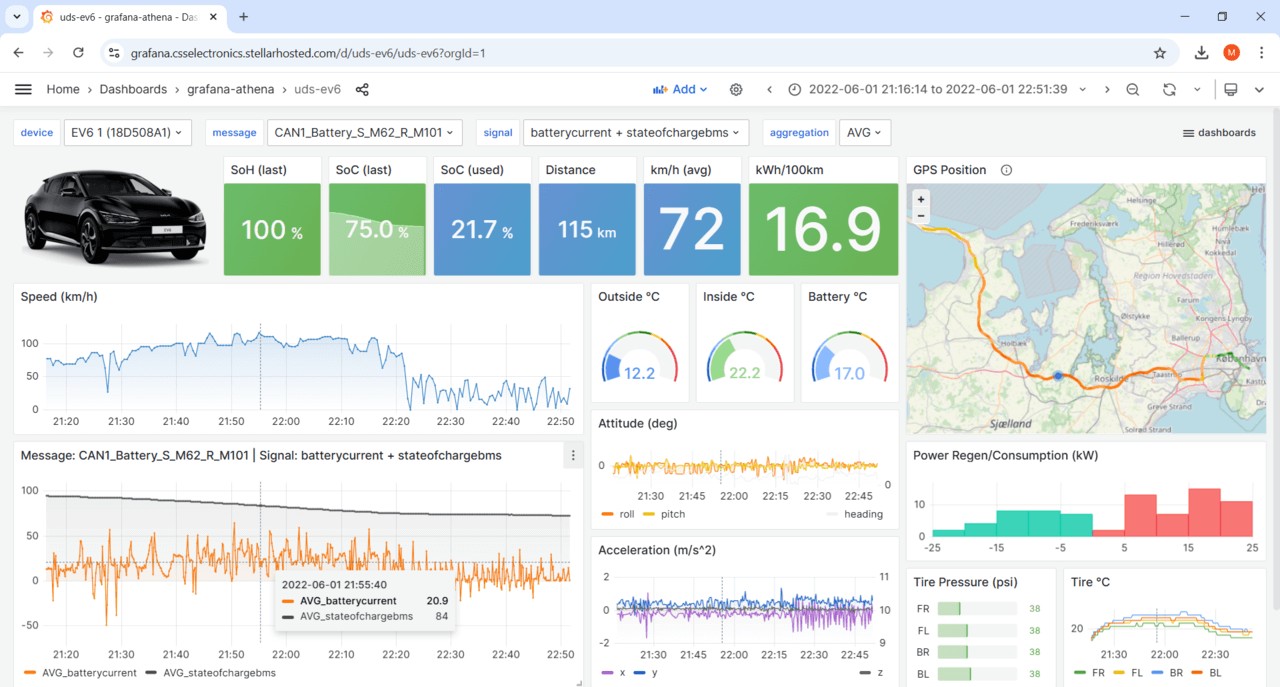
Example 2: Requesting EV State of Charge (SoC) (Multi-Frame)
For parameters like State of Charge in electric vehicles, the data often exceeds a single CAN frame. Multi-frame communication using ISO-TP is necessary. Using UDS service 0x22 and a specific DID (e.g., 0x0101 for a Kia EV6), you can request SoC.
The communication flow involves:
- Single Frame Request: Diagnostic tool sends a request for SoC (SID 0x22, DID 0x0101).
- First Frame Response: ECU responds with a First Frame indicating a multi-frame response and the total data size.
- Flow Control Frame: Diagnostic tool sends a Flow Control frame to initiate data transfer.
- Consecutive Frames: ECU sends multiple Consecutive Frames carrying the SoC data.
- Reassembly and Decoding: The diagnostic tool reassembles the frames and decodes the data. In the Kia EV6 example, after reassembly and applying a scaling factor and offset from a DBC file, the SoC is determined to be 78%.
Example 3: Requesting Vehicle Identification Number (VIN) (Multi-Frame)
The Vehicle Identification Number (VIN) is a crucial identifier. It’s typically retrieved using multi-frame UDS communication.
- OBD2 (SAE J1979): Service 0x09, PID 0x02.
- UDS (ISO 14229-2): Service 0x22, DID 0xF190.
- WWH-OBD (ISO 27145-3): Service 0x22, DID 0xF802.
Example of decoding a Vehicle Identification Number (VIN) obtained via UDS over CAN, showing the conversion from hexadecimal to ASCII characters.
Each method involves a multi-frame request and response sequence similar to the SoC example. The VIN data is returned in ASCII characters within the data payload, requiring hexadecimal to ASCII conversion to read the VIN.
Example 4: Requesting Diagnostic Trouble Codes (DTCs) via WWH-OBD (Multi-Frame)
DTCs are essential for diagnostics. WWH-OBD uses UDS service 0x19 and sub-function 0x42 to request DTCs.
The request includes service 0x19, sub-function 0x42, and parameters specifying the DTC type and masks. The response is a multi-frame message containing a format identifier and then sets of 5 bytes for each DTC, including the DTC code, severity, and status. These DTCs can be further decoded using OBD DTC lookup tools to understand the fault codes.
Applications of UDS Data Logging
UDS data logging has diverse applications:
- Prototype EV Telematics: OEMs use UDS to collect sensor data from prototype electric vehicles for development and testing.
- Predictive Maintenance: Fleet operators and maintenance providers use UDS data, including DTCs and sensor readings, to train predictive maintenance models and optimize vehicle uptime.
- Aftermarket Diagnostics and Tool Development: Understanding UDS is crucial for developing advanced aftermarket diagnostic tools and services.
- Automotive Research and Engineering: Researchers and engineers use UDS data for vehicle performance analysis, reverse engineering, and developing new automotive technologies.
Illustration of a UDS telematics data logger in an electric vehicle, showing data transmission to the cloud.
Conclusion: Mastering ECU Diagnostics with UDS
Unified Diagnostic Services (UDS) is a cornerstone of modern automotive diagnostics. Understanding ECUs and how to communicate with them using UDS is essential for anyone working with today’s complex vehicles. While this article provides a foundation, further exploration of the ISO standards, practical experimentation, and utilizing tools like CAN bus data loggers are key to mastering ECU diagnostics. This information serves as a strong starting point for creating your own “ECU in Cars PPT” or for deepening your knowledge of automotive diagnostic communication.
Ready to delve deeper into UDS data logging? Explore our CANedge data loggers and resources to start your journey.
Buy now Contact us
Recommended for you
CAN TELEMATICS AT SCALE
CANEDGE2 – PRO CAN IoT LOGGER
[