
Are you experiencing car troubles and suspect your Engine Control Unit (ECU) might be the culprit? Knowing How To Check A Car Ecu is a valuable skill for any car owner or DIY enthusiast. This comprehensive guide will walk you through the process of testing your ECU using a multimeter, a tool readily available and essential for automotive diagnostics. We’ll explain what an ECU is, how it works, and provide a detailed, step-by-step method to test its basic functionalities with a multimeter. Let’s get started and empower you to diagnose potential ECU issues.
Understanding the ECU: Your Car’s Brain
The Engine Control Unit (ECU) is essentially the brain of your modern vehicle. It’s a sophisticated computer that manages and controls the engine’s operation, ensuring optimal performance, fuel efficiency, and emissions control. If your ECU malfunctions, it can lead to a cascade of problems, impacting everything from engine performance to basic vehicle operation. In some cases, a faulty ECU can even prevent your car from starting altogether, or result in significantly reduced performance.
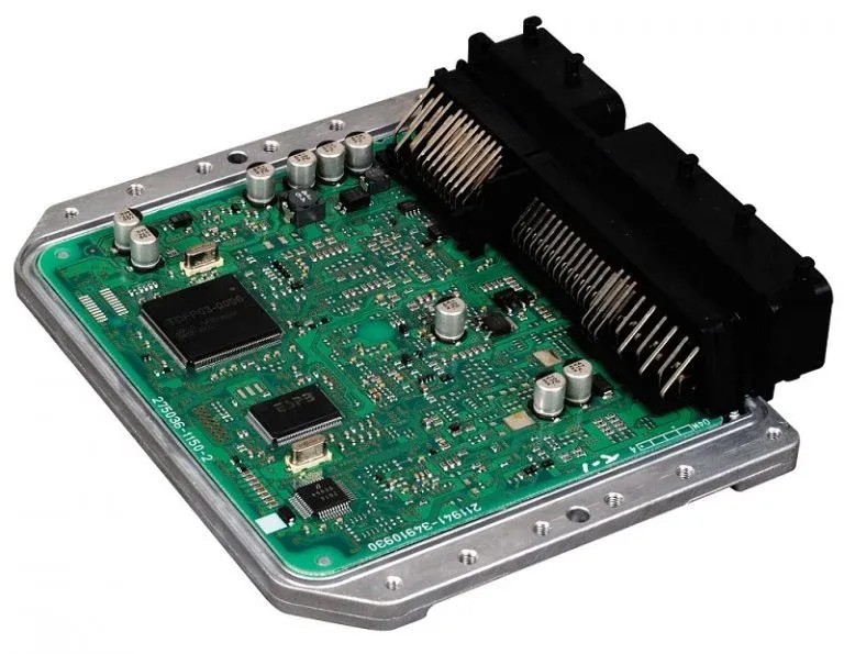
At its core, the ECU is built with microprocessors that process a constant stream of data from various sensors throughout your car. These sensors monitor critical parameters like engine speed, throttle position, air intake temperature, and oxygen levels in the exhaust. The ECU’s hardware includes ceramic substrates, circuit boards, and electronic fittings, all working in concert. A key component is the microcontroller chip, which houses the software that dictates the ECU’s operations and can be reprogrammed if necessary.
There are two main types of ECUs:
- Digital ECUs: These utilize microprocessors to regulate electrical current flow, offering precise control and complex processing capabilities.
- Analog ECUs: Older systems rely on resistors and capacitors to manage current flow. These are less common in modern vehicles.
If you’re uncertain about the type of ECU in your car, consulting your vehicle’s service manual or contacting the manufacturer is always a good idea.
A multimeter can be instrumental in verifying if your ECU is receiving the necessary power to operate correctly. By connecting a multimeter, you can check for proper voltage and continuity, which are crucial for ECU function. If you’re new to using a multimeter, don’t worry! We will provide clear, step-by-step instructions to guide you through the testing process.
How Engine Control Units Function: The Symphony of Sensors and Systems
The ECU’s primary function is to optimize engine performance. It achieves this by continuously analyzing data from a network of sensors and making real-time adjustments to various engine parameters. Based on sensor readings, the ECU calculates the ideal air-fuel mixture for combustion and determines the precise ignition timing for each cylinder. This information is then used to control the fuel injectors and ignition system.
Here’s a glimpse into the sensor data the ECU constantly monitors:
- Engine Speed (RPM): Indicates how fast the engine is rotating.
- Throttle Position: Reflects how much the accelerator pedal is pressed, indicating driver demand for power.
- Manifold Absolute Pressure (MAP): Measures the pressure in the intake manifold, crucial for calculating air density.
- Intake Air Temperature (IAT): The temperature of the air entering the engine, affecting air density and combustion efficiency.
- Oxygen Sensor Signal: Monitors the oxygen content in the exhaust, allowing the ECU to fine-tune the air-fuel mixture for optimal combustion and emissions.
- Knock Sensor Signal: Detects engine knocking or pinging, allowing the ECU to adjust ignition timing to prevent engine damage.
By processing this input data, the ECU ensures the engine operates efficiently and effectively under varying conditions. Beyond air-fuel mixture and ignition timing, the ECU also manages other critical engine functions, such as idle speed control, variable valve timing, and turbocharger boost (if applicable). A malfunctioning ECU can disrupt this intricate system, leading to poor engine performance and various drivability issues.
What is a Multimeter and Why is it Important for ECU Testing?
A multimeter is a versatile electronic measuring instrument that can measure voltage, current, and resistance. It’s an indispensable tool for anyone working with electronics, including automotive electrical systems. For ECU testing, a multimeter allows you to check for proper power supply, ground connections, and signal integrity, helping to pinpoint potential electrical issues that might be affecting the ECU’s performance.
A multimeter typically consists of three main components:
- The Dial (Selector Switch): This allows you to select the type of measurement (voltage, current, resistance) and the measurement range.
- The Probes (Leads): These are used to connect the multimeter to the circuit or component being tested. Typically, there’s a red probe (positive) and a black probe (negative or ground).
- The Meter (Display): This displays the measurement reading. Multimeters come in two main types:
- Digital Multimeters (DMMs): Display readings numerically on an LCD screen, offering accuracy and ease of use.
- Analog Multimeters: Use a needle that moves across a scale to indicate readings. While less common now, they can be useful for visualizing fluctuating signals.
Some advanced multimeters also offer additional features like capacitance measurement and frequency detection. You can find multimeters at most electronics stores and online retailers, making them readily accessible for DIY car diagnostics.
Step-by-Step Guide: How to Test Your Car ECU with a Multimeter
If you’re wondering “how do I check my car’s ECU with a multimeter?”, you’re in the right place. Testing an ECU with a multimeter involves checking its power supply, ground connections, and signal inputs/outputs. This process helps determine if the ECU is receiving power and if its basic electrical circuits are functioning.
Here’s a detailed, step-by-step guide:
Understanding the Basics for ECU Testing:
- Power Supply: The ECU needs a stable power supply to operate. We’ll be checking for the correct voltage reaching the ECU.
- Ground: A proper ground connection is essential for the ECU to complete its electrical circuits. We’ll test for continuity to ensure a good ground.
- Signal Input/Output: The ECU communicates with various sensors and actuators through input and output signals. While a basic multimeter test won’t analyze complex signal patterns, it can help identify potential issues with voltage levels at certain pins.
Step-by-Step Testing Procedure:
-
Safety First: Turn Off the Ignition and Disconnect the Battery (Recommended but not always necessary for basic voltage checks). Turn off your car’s ignition and remove the key. For safety, it’s generally recommended to disconnect the negative battery terminal. However, for basic voltage checks as described in step 6, disconnecting the battery might not be strictly necessary, but always prioritize safety. Consult your vehicle’s service manual for specific safety precautions.
-
Locate the ECU: The ECU is typically located in the engine compartment, but its exact location varies by vehicle make and model. Consult your car’s service manual to pinpoint its location. It might be under the dashboard, behind the glove compartment, or in the engine bay itself.
-
Identify the ECU Connectors: The ECU will have one or more connectors that plug into it. These connectors house the wiring harnesses that carry power, ground, and signals to and from the ECU.
-
Access ECU Pinout Diagram (Crucial): Before testing, you MUST have the ECU pinout diagram for your specific car model and ECU type. This diagram shows the function of each pin on the ECU connector (e.g., power supply, ground, sensor signals, actuator controls). You can usually find this information in your car’s service manual or online auto repair databases. Testing without a pinout diagram can lead to incorrect measurements and potentially damage the ECU.
-
Set Up Your Multimeter for DC Voltage Measurement: Turn on your multimeter and set the dial to measure DC voltage (DCV). Select a voltage range that is appropriate for automotive systems, typically 20V or similar, which will cover the standard 12V or 14V systems in most cars.
-
Test for ECU Power Supply:
- Identify Power Pins: Using your ECU pinout diagram, locate the pin(s) designated as the power supply (usually labeled as VCC, +B, or similar).
- Connect Multimeter: Connect the red probe of your multimeter to the identified power supply pin on the ECU connector. Connect the black probe to a known good ground point on the vehicle chassis or the negative battery terminal (if connected).
- Turn Ignition to “ON” (but do not start the engine): Turn your ignition key to the “ON” position (or accessory position, depending on your vehicle) without starting the engine. This will power up the ECU.
- Read Voltage: Observe the voltage reading on your multimeter. You should typically see a reading close to battery voltage, generally between 12 to 14 volts when the engine is not running and around 13.5 to 14.5 volts when the engine is running (charging system active).
-
Test for ECU Ground:
- Identify Ground Pins: Using your ECU pinout diagram, locate the pin(s) designated as ground (usually labeled as GND or ground).
- Set Multimeter to Continuity Test: Change your multimeter setting to the continuity test mode (often represented by a diode symbol or a sound wave symbol). This mode checks for a continuous electrical path.
- Connect Multimeter: Connect one probe of your multimeter to the identified ground pin on the ECU connector. Connect the other probe to a known good ground point on the vehicle chassis.
- Check for Continuity: Your multimeter should indicate continuity. On a digital multimeter, this is usually indicated by a reading close to 0 ohms or a beep sound. This confirms a good ground connection.
-
Basic Signal Input/Output Checks (Advanced – Requires Pinout Diagram and Understanding of Signals): With the pinout diagram, you can identify sensor input and actuator output pins. However, testing these signals with just a multimeter can be complex and may not provide conclusive results without further knowledge of the expected signal types and ranges. For basic checks:
- Voltage Checks: You might be able to check for the presence of voltage on some signal pins when the ignition is “ON” or the engine is running. Consult the pinout diagram and relevant repair information for expected voltage levels on specific pins.
- Resistance Checks (with caution and proper procedure): In some cases, you might be able to measure resistance on certain sensor circuits (e.g., checking sensor resistance). Always disconnect the ECU before measuring resistance on sensor circuits to avoid damaging the ECU or sensors. Refer to your service manual for proper procedures and acceptable resistance ranges.
-
Interpret Results:
- No Power or No Ground: If you don’t get proper voltage readings on the power pins or continuity on the ground pins, it indicates a problem with the ECU’s power supply or ground circuit, which needs to be investigated further (wiring issues, fuses, relays). This doesn’t necessarily mean the ECU is faulty, but it’s not receiving the power it needs.
- Power and Ground OK, but Still Suspect ECU: If power and ground are confirmed, but you still suspect an ECU issue based on symptoms, further diagnostic steps are needed. A multimeter alone cannot fully diagnose a complex ECU malfunction. You might need an OBD-II scanner for code reading, live data analysis, or professional diagnostic tools for deeper ECU testing.
Important Cautions:
- Always use the correct ECU pinout diagram for your specific vehicle.
- Be careful when probing ECU connector pins. Avoid forcing probes or damaging pins.
- Do not perform resistance measurements on ECU pins while the ECU is connected to power.
- Basic multimeter tests are limited. They can confirm power and ground issues but cannot fully diagnose internal ECU faults or complex signal problems.
- If you are not comfortable working with automotive electrical systems, it’s best to consult a qualified automotive technician.
Common Symptoms of a Failing ECU
While multimeter testing can help rule out basic power and ground issues, recognizing the symptoms of a bad ECU is also crucial for diagnosis. Here are some common signs that your ECU might be failing:
-
Engine Performance Issues:
- Erratic Engine Behavior: This can manifest as reduced engine power, poor acceleration, engine stalling, misfires, rough idling, or hesitation.
- Check Engine Light (CEL) Illumination: A constantly lit CEL is a common indicator of ECU problems. The ECU may be struggling to control the engine, triggering fault codes that illuminate the light.
-
Emission Problems: A faulty ECU can disrupt the air-fuel mixture and emissions control systems, leading to:
- Increased Exhaust Emissions: You might notice your car failing emissions tests or observe excessive smoke from the exhaust.
- Poor Fuel Economy: An improperly functioning ECU can lead to inefficient fuel consumption.
-
Starting and Drivability Problems:
- Difficulty Starting: In severe cases, a bad ECU can prevent the engine from starting at all.
- Stalling: The engine might stall unexpectedly while driving.
- Transmission Issues (in some vehicles): In vehicles where the ECU also controls the automatic transmission, ECU problems can lead to shifting problems.
-
Other Unusual Symptoms:
- Intermittent Problems: ECU failures can sometimes be intermittent, meaning problems come and go, making diagnosis challenging.
- Complete Engine Failure (in extreme cases): In rare situations, a severely failed ECU can lead to complete engine shutdown.
Note: Many of these symptoms can also be caused by other issues (sensor failures, wiring problems, mechanical problems). Therefore, proper diagnosis, including code scanning and potentially more advanced ECU testing, is essential to confirm an ECU failure.
FAQs About ECU Testing
Question 1: How else can I test an ECU beyond using a multimeter?
Answer: Beyond multimeter tests, you can use more advanced methods like:
- OBD-II Scanner: An OBD-II scanner is essential for reading diagnostic trouble codes (DTCs) stored in the ECU’s memory. These codes can provide valuable clues about potential ECU or sensor problems. Scanners can also display live data from sensors, allowing you to monitor ECU inputs and outputs in real-time.
- ECU Simulators and Bench Testing: For more in-depth testing, specialized ECU simulators can mimic sensor inputs and system loads, allowing technicians to test the ECU’s responses and outputs in a controlled environment outside the car. Diagnostic software and tools are used in conjunction with simulators to monitor ECU parameters and analyze its behavior.
Question 2: What are the risks if I don’t test the ECU correctly?
Answer: Improper ECU testing can lead to several risks:
- Damage to the ECU: Incorrect probing, short circuits, or applying excessive voltage or current can damage the delicate electronics within the ECU, potentially requiring expensive repairs or replacement.
- Voiding Warranty: Tampering with the ECU or performing unauthorized tests might void your vehicle’s warranty in some cases.
- Misdiagnosis: Incorrect test procedures or misinterpretation of results can lead to misdiagnosis, resulting in unnecessary parts replacements and continued problems.
Always follow proper procedures, use the correct tools, and consult service information to minimize risks.
Question 3: Can ECU faults be prevented?
Answer: While ECUs are generally robust, preventative maintenance can help minimize the risk of faults:
- Regular Vehicle Maintenance: Following your vehicle’s recommended maintenance schedule helps ensure all systems are functioning properly, reducing stress on the ECU.
- Proper Battery Maintenance: A healthy battery and charging system are crucial for stable ECU operation. Ensure your battery is in good condition and the charging system is working correctly.
- Avoid Water Damage: Protect the ECU from water intrusion, as moisture can damage its sensitive electronics.
- Professional Diagnostics for Electrical Issues: If you experience any electrical problems or warning lights, have them diagnosed by a qualified technician promptly to prevent potential cascading issues that could affect the ECU.
Question 4: What happens if the ECU fuse is blown?
Answer: The ECU is protected by a fuse in the vehicle’s fuse box. If the ECU fuse blows, it means there was an overcurrent or short circuit in the ECU’s power circuit. A blown ECU fuse can cause:
- Engine No Start: Without power, the ECU cannot function, preventing the engine from starting.
- Engine Stalling: If the fuse blows while driving, the engine will abruptly stall.
- Other Electrical Malfunctions: Depending on the circuit protected by the fuse, other electrical systems might also be affected.
If you suspect a blown ECU fuse:
- Locate the ECU fuse in your car’s fuse box diagram.
- Inspect the fuse: A blown fuse will usually have a broken wire inside.
- Replace the fuse with a fuse of the same amperage rating.
- If the fuse blows again immediately, there is likely a short circuit in the ECU’s power circuit that needs to be diagnosed by a technician. Do not keep replacing fuses without finding the underlying cause, as this could damage the ECU or wiring.
Wrapping Up: Empowering Your Car Diagnostic Skills
Understanding how to test a car ECU with a multimeter is a valuable skill for car owners and DIY mechanics. While basic multimeter tests are limited in scope, they can effectively check for fundamental power supply and ground issues, helping you narrow down potential problems. Combined with knowledge of ECU symptoms and the use of OBD-II scanners, you can take a more informed approach to diagnosing car troubles.
Remember, safety and accuracy are paramount when working with automotive electrical systems. Always consult your vehicle’s service manual, use the correct tools, and proceed cautiously. If you encounter complex issues or are uncomfortable performing these tests yourself, seeking professional help from a qualified automotive technician is always recommended.
Have you tried testing your car’s ECU with a multimeter? Share your experiences or questions in the comments below!
Related Articles
How to Test ECU with Multimeter: Complete Guide
Multimeter Not Reading Current [How to Fix]
Multimeter Not Reading DC Voltage: How to Fix it?