
Diagnosing car issues can often lead you to the Engine Control Unit (ECU), the brain of your vehicle. If you suspect an ECU problem, testing it is a crucial step. This guide will walk you through how to test your car’s ECU using a multimeter, a fundamental tool for automotive diagnostics. We’ll cover what an ECU is, how it works, and provide a detailed, step-by-step method for testing it effectively.
Understanding the ECU: Your Car’s Brain
What is a Car ECU?
ECU stands for Engine Control Unit, sometimes also referred to as the Powertrain Control Module (PCM) when it controls both engine and transmission. Think of it as the central computer that manages your car’s engine performance. A malfunctioning ECU can lead to a variety of drivability problems, ranging from poor engine performance to a complete no-start condition.
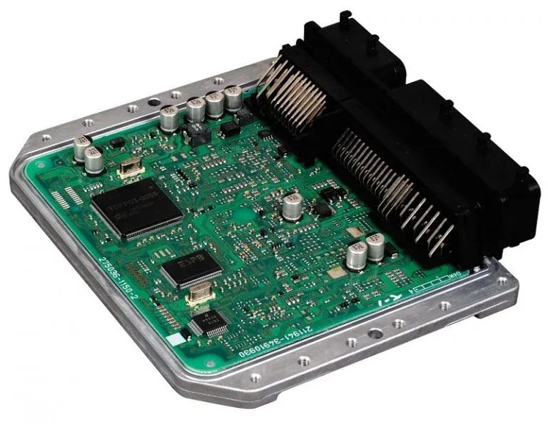
Inside the ECU, microprocessors analyze data from numerous sensors throughout your vehicle. These sophisticated components include ceramic substrates, circuit boards, and various electronic fittings. At the heart of it is a microcontroller chip, which houses the operating software and can sometimes be reprogrammed.
ECUs are broadly classified into two types:
- Analog ECUs: These older types use resistors and capacitors to regulate current flow.
- Digital ECUs: Modern vehicles predominantly use digital ECUs, where microprocessors control the current flow for more precise engine management.
If you’re unsure about the type of ECU in your car, your vehicle’s service manual or a call to the manufacturer can provide this information.
A multimeter is invaluable for verifying if your ECU is receiving the necessary power to operate correctly. If you’re new to using a multimeter, don’t worry; we’ll guide you through each step of the testing process.
How Engine Control Units Operate
The ECU’s primary function is to optimize engine performance, fuel efficiency, and emissions. It achieves this by constantly monitoring sensor data and adjusting engine parameters in real-time. Based on the information it receives, the ECU calculates the ideal air-fuel mixture and ignition timing, controlling the fuel injectors and ignition system accordingly.
The ECU constantly processes input from a network of sensors, including:
- Engine Speed (RPM): Indicates how fast the engine is rotating.
- Throttle Position: Reflects the driver’s demand for power.
- Manifold Absolute Pressure (MAP): Measures air pressure in the intake manifold.
- Intake Air Temperature: Monitors the temperature of incoming air.
- Oxygen Sensor Signal: Provides feedback on the exhaust gas mixture, crucial for fuel mixture control.
- Knock Sensor Signal: Detects engine knocking or pinging, allowing the ECU to adjust ignition timing for engine protection.
Using this sensor data, the ECU determines the optimal air-fuel ratio and ignition timing for various driving conditions. It then precisely controls the fuel injectors to deliver the correct amount of fuel and manages the ignition system to ensure efficient combustion. Beyond these core functions, the ECU also oversees other engine-related systems, such as idle speed control and emissions control systems. A faulty ECU can disrupt these processes, leading to significant engine performance and drivability issues.
What is a Multimeter and Why You Need It for ECU Testing
Understanding the Multimeter
A multimeter is an essential electronic measuring instrument used to measure voltage, current, and resistance. It’s a versatile tool for diagnosing electrical problems in various electronic components, including car ECUs. For testing an ECU, a multimeter is primarily used to check for proper power supply, ground connections, and signal integrity.
A multimeter consists of three main parts:
- The Dial (or Selector Switch): Used to select the measurement type (voltage, current, resistance) and the measurement range.
- The Probes (Leads): These are used to connect the multimeter to the circuit or component being tested. Typically, there’s a red probe (positive) and a black probe (negative/ground).
- The Display (Meter): Shows the measurement reading. Multimeters are available in both digital (numeric display) and analog (needle display) types. Digital multimeters are generally preferred for their accuracy and ease of reading. Some advanced multimeters also offer features like capacitance measurement and frequency detection, which can be useful in more complex diagnostics.
Multimeters are readily available at most electronics stores and online retailers, making them accessible for both professional mechanics and DIY enthusiasts.
Step-by-Step Guide: How to Test Your Car ECU with a Multimeter
If you’re experiencing car problems and suspect the ECU might be the culprit, testing it with a multimeter is a logical diagnostic step. This process involves checking the ECU’s power supply, ground connections, and input/output signals.
Here’s a detailed guide on how to perform these tests:
A multimeter allows you to analyze the ECU’s:
- Power Supply: Ensures the ECU is receiving the correct voltage.
- Ground: Verifies proper ground connection, which is crucial for circuit completion.
- Signal Input/Output: Checks the communication pathways between the ECU and various sensors and actuators in the vehicle.
Testing the ECU Power Supply:
- Set up your Multimeter: Turn the multimeter dial to the DC Voltage setting (usually marked as “VDC” or “DCV”). Select a range that is higher than your car’s battery voltage (e.g., 20V DC range).
- Locate ECU Power Pins: Refer to your vehicle’s wiring diagram or ECU pinout diagram (often found in service manuals or online resources specific to your car model). Identify the pins that supply power to the ECU. These are typically labeled for battery voltage (B+) or ignition voltage.
- Connect Multimeter Probes:
- Connect the red probe of the multimeter to the identified power supply pin on the ECU connector.
- Connect the black probe to a known good ground on the vehicle chassis or the negative battery terminal.
- Check Voltage Reading: Turn the ignition key to the “ON” position (but do not start the engine unless instructed otherwise in your specific vehicle’s testing procedure). Observe the voltage reading on the multimeter. It should typically read close to battery voltage (around 12-14.5V). If the reading is significantly lower or zero, there may be a problem with the power supply circuit to the ECU (e.g., blown fuse, wiring issue).
Testing the ECU Ground Connection:
- Set up your Multimeter: Set the multimeter to the Continuity test mode (usually symbolized by a diode symbol or a speaker symbol). This mode will beep if there is a continuous electrical path (low resistance).
- Locate ECU Ground Pins: Using your vehicle’s wiring diagram, identify the ground pins on the ECU connector. These are often labeled as “GND” or “Ground.”
- Connect Multimeter Probes:
- Connect one probe of the multimeter (either red or black) to the identified ground pin on the ECU connector.
- Connect the other probe to a known good ground point on the vehicle chassis (bare metal part of the car’s frame).
- Check for Continuity: The multimeter should beep, indicating continuity and a good ground connection. If there is no beep (or the resistance reading is high in Ohms mode if your multimeter doesn’t have continuity beep), there’s likely a ground fault, which needs to be investigated.
Testing ECU Input/Output Signals (More Advanced):
Testing input/output signals requires more specific knowledge of your vehicle’s ECU and sensor operation. You’ll need:
- Vehicle-Specific Wiring Diagrams: Essential for identifying signal pins and expected voltage ranges.
- Understanding of Sensor Types: Knowing how different sensors (e.g., MAP sensor, TPS, O2 sensor) operate and the type of signals they send (voltage, frequency, etc.).
General Steps for Signal Testing (Example – Analog Voltage Signal):
- Identify Signal Pin: Using wiring diagrams, locate the pin on the ECU connector for the specific sensor signal you want to test (e.g., MAP sensor signal).
- Set Multimeter to Voltage: Set your multimeter to the appropriate DC Voltage range.
- Back-Probe the Connector: Carefully back-probe the ECU connector pin while it’s still connected to the ECU (avoid damaging the connector or wires). Connect the red probe to the signal wire and the black probe to a good ground.
- Observe Signal Voltage: Turn the ignition ON (or start the engine if required for the specific signal). Measure the voltage reading. Compare this reading to the expected voltage range specified in your service manual or online resources for that sensor and operating condition (e.g., idle, throttle open). Incorrect voltage readings can indicate sensor malfunction, wiring problems, or ECU issues.
Important Safety Precautions:
- Disconnect Ignition: Always turn off the ignition and remove the key before disconnecting or connecting ECU connectors.
- Battery Safety: While testing, be mindful of battery terminals and avoid accidental shorts.
- Wiring Diagrams: Always use accurate wiring diagrams specific to your vehicle model.
- Back-Probing: Use caution when back-probing connectors to avoid damaging wires or pins.
- Consult a Professional: If you are unsure about any step or encounter unexpected readings, consult a qualified automotive technician.
Simplified Step-By-Step for Basic ECU Power Test:
If you want to perform a quick check of ECU power, follow these simplified steps:
- Turn off Ignition: Remove the ignition key and ensure the car is completely off.
- Locate ECU: The ECU is typically located in the engine bay or under the dashboard. Consult your car’s service manual for the exact location.
- Identify ECU Connectors: Locate the connectors plugged into the ECU.
- Battery Connection (Simplified): (For a basic voltage check, this simplified method can be used with caution. For thorough testing, refer to the detailed steps above and wiring diagrams). Carefully identify a pin that is likely a power pin on the ECU connector (often thicker wires). Connect the black probe of your multimeter to the negative battery terminal of your car. Connect the red probe to the suspected power pin on the ECU connector.
- Set Multimeter to Voltage: Set your multimeter to read DC Voltage (20V range).
- Turn Ignition ON (Briefly): Turn your car’s ignition to the “ON” position (do not start the engine).
- Read Voltage: Observe the voltage reading on the multimeter. It should be in the range of approximately 12 to 14.5 volts if the ECU is receiving power.
- Voltage Out of Range: If the voltage reading is outside this range, it suggests a power supply issue to the ECU, and further, more detailed testing is required using wiring diagrams and proper pin identification.
Note: This simplified method is a very basic check. For accurate and safe ECU testing, always refer to detailed wiring diagrams and follow the more comprehensive steps outlined earlier, including proper pin identification and ground testing.
Common Symptoms of a Faulty ECU
Recognizing the symptoms of a bad ECU can help you determine if testing is necessary. Here are some common indicators:
Erratic Engine Behavior:
Unusual engine performance is a primary symptom of a potential ECU issue. This can manifest in various ways:
- Reduced Engine Power: The engine may feel sluggish and lack its usual power.
- Poor Acceleration: The car may accelerate slowly or hesitate during acceleration.
- Engine Stalling: The engine may stall unexpectedly, especially at idle or low speeds.
- Engine Misfiring: You might experience rough idling and misfires, which can be felt as vibrations or jerking. These symptoms often indicate that the ECU is not properly controlling fuel delivery or ignition timing. If you notice any of these engine performance issues, it’s wise to have the ECU checked.
Check Engine Light Illumination:
A constantly lit Check Engine Light (CEL) is a frequent sign of ECU problems. While the CEL can be triggered by numerous issues, a malfunctioning ECU is a significant possibility. If the engine control system is struggling to manage the engine due to an ECU fault, the CEL will often illuminate to alert you to a potential problem. When the CEL is on, it’s crucial to use an OBD-II scanner to read the trouble codes stored in the ECU, which can provide valuable clues about the nature of the fault, including potential ECU-related codes.
Increased Emissions:
A failing ECU can lead to increased vehicle emissions. Since the ECU controls the air-fuel mixture and combustion process, a malfunctioning ECU can disrupt these parameters, resulting in inefficient combustion and higher levels of pollutants in the exhaust. You might notice increased smoke from the exhaust pipe, or your car may fail an emissions test. Increased emissions are not only environmentally unfriendly but can also indicate underlying engine control problems, possibly stemming from the ECU.
FAQs About ECU Testing
Question 1: Beyond a multimeter, how else can I test an ECU?
Answer: While a multimeter checks basic power and ground, more comprehensive ECU testing often involves “bench testing.” This method simulates the car’s electrical system and sensor inputs to the ECU on a test bench. Specialized tools like ECU simulators and diagnostic scanners can communicate with the ECU, allowing technicians to monitor parameters, read fault codes, and test outputs in a controlled environment. This is especially useful for diagnosing intermittent faults or verifying ECU functionality outside the vehicle.
Question 2: What risks are involved if I skip multimeter testing and directly assume ECU failure?
Answer: Skipping basic multimeter tests and immediately assuming ECU failure can be risky and costly. You might replace a perfectly good ECU when the problem lies elsewhere, such as in the wiring, sensors, or actuators connected to the ECU. Replacing an ECU unnecessarily is an expensive mistake. Furthermore, without proper diagnosis, you might not identify the root cause of the problem, and the issue may persist even after ECU replacement. Always perform basic electrical tests with a multimeter to rule out simpler problems before concluding ECU failure.
Question 3: Can ECU faults be prevented?
Answer: While ECUs are generally robust, preventative maintenance can contribute to their longevity. Ensuring your vehicle’s electrical system is in good condition is crucial. Maintain proper battery voltage, check for corrosion in wiring and connectors, and protect the ECU from physical damage and moisture. Regular vehicle servicing, including checking engine coolant and oil levels, also indirectly supports ECU health by ensuring the engine operates within its designed parameters. While not directly preventing internal ECU component failure, these measures help minimize external factors that could stress the ECU.
Question 4: What happens when an ECU fuse blows?
Answer: If the ECU fuse blows, it interrupts the power supply to the ECU, potentially causing a range of issues. A blown ECU fuse can prevent the engine from starting, cause the car to stall, or lead to various electrical malfunctions. If you suspect an ECU fuse problem, locate the fuse box (usually under the dashboard or in the engine bay), identify the ECU fuse (refer to the fuse box diagram), and check if it’s blown (broken filament). Always replace a blown fuse with one of the same amperage rating. Repeatedly blown fuses indicate a short circuit or an underlying electrical problem that needs to be diagnosed and repaired, not just fuse replacement.
Wrapping Up: Multimeter Testing for ECU Diagnostics
Multimeters are indispensable tools for automotive electrical diagnostics. They enable you to check for continuity, resistance, voltage, and current in circuits and components, including the crucial Engine Control Unit. If your car is exhibiting symptoms like engine performance issues, a persistent Check Engine Light, or increased emissions, testing the ECU with a multimeter is a valuable step in the diagnostic process.
By using a multimeter to test for voltage and ground at the ECU, you can identify potential power supply problems or ground faults that might be contributing to the issue. While multimeter testing is a fundamental step, remember that comprehensive ECU diagnosis might require more advanced techniques and tools, especially for signal analysis and internal ECU faults. This guide has provided you with the essential knowledge on how to test your car ECU with a multimeter, empowering you to take a proactive role in vehicle maintenance and troubleshooting. Have you used a multimeter to test an ECU before? Share your experiences or questions in the comments below!
Related Articles for Further Reading
How to Test ECU with Multimeter: Complete Guide
Multimeter Not Reading Current [How to Fix]
Multimeter Not Reading DC Voltage: How to Fix it?